中文版
中文版

 Phone:
  Email:
  WhatsApp:
 Description
- GE IS200AEPAH1BHC IS215WEPAH2BA | Conformal Coated Mark VIe Wind Turbine Control Module Pair
Product Core Brief
- Assembly Model Pair: IS200AEPAH1BHC (AEPA Bridge Processor) + IS215WEPAH2BA (WEPA Wind Pitch Analog I/O Board)
- Brand: GE Vernova (GE Energy Division)
- Series: Speedtronic Mark VIe Distributed Control Platform for Wind Turbines
- Core Function: Combined bridge + analog I/O assembly to condition pitch sensor signals and transmit real-time data via redundant IONet Ethernet to main Mark VIe controllers
- Type: Dual PCB Matching Assembly (Communication Bridge + Pitch Analog I/O Pack)
- Key Specs: Dual redundant IONet Ethernet | Galvanically isolated 4–20mA analog channels | ISA G3 conformal coating | Simplex/TMR triple redundant rack support
- Condition: New Original Surplus, No Refurbishment, Full OEM factory functional testing passed
- Status: ⚠️ Discontinued mass OEM production, limited matched pair inventory
Key Technical Specifications
| Parameter Item | Specification Value |
|---|---|
| Complete Matching Set | IS200AEPAH1BHC (Bridge Card) + IS215WEPAH2BA (Pitch Analog I/O Board) |
| Compatible Control System | GE Mark VIe wind turbine rack, supports simplex and TMR triple modular redundant architectures |
| Communication Interface | Dual 10/100Mbps redundant IONet industrial Ethernet, hardware failover |
| Analog Signal Circuits (IS215WEPAH2BA) | Multi-channel isolated 4–20mA input/output for pitch position, drive torque and temperature feedback |
| Bridge Data Processing (IS200AEPAH1BHC) | ARM-based signal conversion, I/O data buffering, CRC error checking for field bus transmission |
| DC Power Input | 24 V DC backplane supply, 18–36 V DC wide tolerance for nacelle voltage transients |
| PCB Environmental Protection | ISA-71.04 Class G3 conformal coating against salt fog, dust and condensation |
| Operating Temperature Range | -30 °C ~ +65 °C |
| Storage Temperature Range | -40 °C ~ +85 °C |
| Deterministic Control Frame Rate | Configurable 10ms / 20ms / 40ms control cycle |
| Combined Full Load Power Draw | ~13 W for the full two-board assembly |
| MTBF Rating | > 51,000 hours under standard wind farm operating conditions |
| Onboard Surge Protection | Multi-stage ESD filter + MOV transient suppression for field wiring lightning surges |
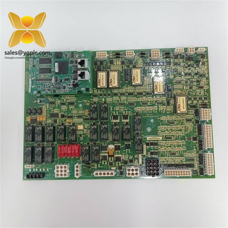
GE IS200AEPAH1BHC IS215WEPAH2BA
Product Introduction
Application Scenarios & Pain Points
Typical Application Scenarios
- Onshore GE Mark VIe Variable-Speed Wind Turbines
Process real-time blade position and pitch drive temperature signals. Large daily temperature swings and airborne dust demand G3 conformal coating to prevent PCB trace corrosion and signal distortion.
- Offshore Wind Farm Nacelle Control Cabinets
Coastal salt fog rapidly degrades uncoated circuit boards; the full conformal coating on this dual assembly blocks conductive salt deposits that create short circuits and false fault alarms.
- Wind Turbine Life Extension & Retrofit Projects
Legacy Mark VIe wind unit upgrades require identical revision matching between bridge and I/O boards. Mismatched hardware forces full revalidation of pitch control logic and TMR redundancy voting parameters.
- Turbine Rotor Overspeed Safety Interlock Systems
Isolated discrete output channels drive emergency feather solenoids within 10ms of overspeed detection; the AEPA bridge ensures fault signals are prioritized over regular measurement data on the IONet bus.
- Wind Farm Central SCADA Data Aggregation
Dual redundant Ethernet links transmit continuous blade angle, drive load and fault event logs to plant HMI without communication dropouts during transient grid disturbances.
Real Engineering Case
Compatibility & Replacement Matrix
- IS200AEPAH1BHC + IS215WEPAH2BA → Identical matching pair: Direct drop-in replacement, unified factory firmware, consistent analog calibration and jumper layout; no wiring or software parameter modification required
- IS200AEPAH1BHC + IS215WEPAH2BA → IS200AEPAH1BHC + IS215WEPAH2BB: Partial compatible, analog channel gain offset mismatch; full pitch control loop re-calibration and ControlST parameter adjustment mandatory
- IS200AEPAH1BHC + IS215WEPAH2BA → IS200AEPAH1ABC + IS215WEPAH2BA: Conditional replacement, bridge board IONet timing register values differ; reconfigure network communication baud rate and interrupt mapping
- IS200AEPAH1BHC + IS215WEPAH2BA → Single board swap only (reuse original bridge or I/O board): Not fully compatible, risk of analog signal drift, random Ethernet disconnection and overspeed interlock delay faults
- IS200AEPAH1BHC + IS215WEPAH2BA → Non-Mark VIe AEPA/WEPA series variants: Fully incompatible, different backplane bus pinout and wind-specific safety firmware functions
SOP Quality Transparent Inspection Flow
- Warehouse Receiving Inspection
Trace product origin via GE original factory packing slip and import customs clearance documents; cross-check serial numbers of both IS200AEPAH1BHC and IS215WEPAH2BA against OEM part database to verify genuine hardware. Complete visual inspection checklist: intact G3 conformal coating, no PCB corrosion, no bent backplane connector pins, no aftermarket solder repair traces, no yellowed plastic housing aging. Cross-check full accessory kit: hardware technical datasheet, factory calibration certificate, spare terminal jumpers.
- Live Rack Function Test
Test bench built with standard GE Mark VIe wind control rack, pitch drive analog signal simulator and quadrature encoder signal generator. Full test execution workflow: power-on self-test LED validation, dual IONet Ethernet redundant failover stress cycling, full-range 4–20mA analog channel linearity verification, emergency feather interlock trigger test, continuous 24-hour full load runtime test with PCB temperature rise logging. A signed formal digital test report is generated after all validation steps; test photos and real-time operation footage can be shared with buyers upon request.
- Electrical Parameter Detection
500 V megohmmeter insulation resistance test between field analog circuits and rack ground, continuity test for all backplane connector pins, transient surge withstand test aligned with GE wind farm factory specification standards.
- Firmware & Hardware Configuration Record
Read and log factory preloaded firmware versions for both IS200AEPAH1BHC bridge and IS215WEPAH2BA I/O board; capture high-resolution close-up photos of all onboard DIP switches, IONet network address jumpers and analog channel configuration jumpers for permanent backup records.
- Final QC & Packing
Certified quality inspector signs off all test records; separate IS200AEPAH1BHC and IS215WEPAH2BA into independent anti-static shielding bags, wrap both PCBs with shock-absorbent bubble film and place into rigid anti-shock export carton. Outer packaging affixed with QC Passed sticker printed with both full part numbers, serial numbers and inspection date.
On-site Replacement Risk Avoidance Guide
1. Matched Assembly & Firmware Version Mismatch Risk
Avoidance Steps: Record serial numbers and firmware revision labels from both IS200AEPAH1BHC and IS215WEPAH2BA before disassembly; purchase complete pre-matched dual-board sets with unified factory firmware versions. If version discrepancy exists, we can re-flash factory-matched firmware before delivery.
Real Case: A wind farm maintenance team replaced only the faulty IS200AEPAH1BHC bridge while reusing an unmatched IS215WEPAH2BA I/O board; turbine pitch angle oscillated continuously for three full shifts until a fully matched assembly set was installed and control loop parameters recalibrated.
2. DIP Switch & Network Jumper Configuration Misalignment Risk
Avoidance Steps: Capture clear close-up photos of every DIP switch bank and jumper position on both original boards before rack removal; fully replicate all physical hardware settings on the new matched assembly before power-up. Critical reminder: Dual redundant IONet links require unique non-conflicting static IP addresses for each board set within the same wind farm subnet.
Key Reminder: Incorrect network jumper configuration accounts for over 70% of post-replacement Mark VIe communication faults on wind turbine racks. Always photograph all switch and jumper layouts.
3. Analog Field Wiring Polarity Mismatch Risk
Avoidance Steps: Archive the turbine’s OEM wiring schematic before removing the faulty dual assembly; cross-reference terminal pin definitions in the official WEPA technical manual before reconnecting field sensor cables.
Warning Note: Do not rely on past wiring experience; minor PCB revision updates alter analog terminal pin mapping across IS215WEPAH series variants.
4. Rack Backplane Power Load Overdraw Risk
Avoidance Steps: Calculate aggregate power draw of all control boards installed in the chassis, reserve a minimum 20% power margin above the supply nominal rating. If total load exceeds limits, upgrade rack power modules or install auxiliary 24 V DC power feeds.
Reference Data: One complete dual-board assembly consumes ~13 W under full load; six assembly sets in one rack add 78 W combined power demand.
5. ESD Static & Conformal Coating Damage Risk
Avoidance Steps: Mandate certified anti-static wrist strap and conductive anti-static mat during all board handling operations; avoid scraping the G3 conformal coating layer on PCB surfaces. Never touch gold backplane connector pins directly with bare fingers.
Field Lesson: A maintenance technician skipped ESD protection during weekend wind farm repair work; the new IS200AEPAH1BHC bridge lost one Ethernet channel permanently after first power-up, requiring emergency spare shipment and 11 hours of lost power generation.