中文版
中文版

 Phone:
  Email:
  WhatsApp:
 Description
- Model: 810-068158-014
- Brand: LAM Research
- Series: LAM Semiconductor Equipment Control Hardware
- Core Function: Interfaces the tool controller with robot systems
- Type: Node Robot Interface Board / PCBA
- Key Specs: Robot interface; multi-channel I/O; semiconductor equipment application
- Application: Wafer handling and equipment automation
- Board Function: Robot status, control, and signal interfacing
- Form Factor: PCB assembly
- Typical Environment: Semiconductor fabrication equipment
- Stocking Role: Critical automation spare
- Condition: Verify New Surplus, Used, or Refurbished status before purchase
Available market references identify 810-068158-014 as a Node Robot Interface Board used in LAM Research semiconductor equipment. However, third-party listings provide conflicting electrical and dimensional specifications, so values such as voltage, frequency, dimensions, and weight should not be treated as confirmed manufacturer specifications without the applicable LAM documentation or nameplate.
Product Introduction
LAM 810-068158-014 is identified in current market references as a Node Robot Interface Board for LAM Research semiconductor equipment. The PCBA provides an interface between equipment control electronics and wafer-handling robot functions, where signal exchange and equipment status are essential to automated material handling.
For spare-parts planning, this is better treated as a specialized, low-volume control PCB rather than a generic I/O card. Public listings disagree on several technical parameters, so procurement should focus on exact part-number matching, board revision, connector arrangement, physical condition, and traceability before release to the fab floor.
Key Technical Specifications
| Parameter | Specification |
|---|---|
| Manufacturer | LAM Research |
| Part Number | 810-068158-014 |
| Product Type | Node Robot Interface Board |
| Assembly Type | PCBA / Interface Control Board |
| Primary Function | Robot interface and equipment signal exchange |
| Application | Semiconductor manufacturing equipment |
| System Role | Interface between control system and robot subsystem |
| I/O Function | Robot status and control signal interfacing |
| Communication | Configuration-dependent; verify equipment documentation |
| Supply Voltage | Not confirmed — verify against LAM documentation |
| Operating Temperature | Not confirmed — verify against equipment manual |
| Dimensions | Not confirmed — verify actual board/mechanical drawing |
| Weight | Not confirmed — verify actual supplied assembly |
| Certification | Verify from actual nameplate/documentation |
| Installation | Equipment-specific board slot/interface |
| Condition | New / Used / Refurbished — confirm before purchase |
Some third-party sources claim 24 VDC operation and approximately 0.4 kg, while other listings claim 220 V, 0.35 kg, or substantially different physical data. These conflicts are a clear reason not to publish those figures as guaranteed specifications.
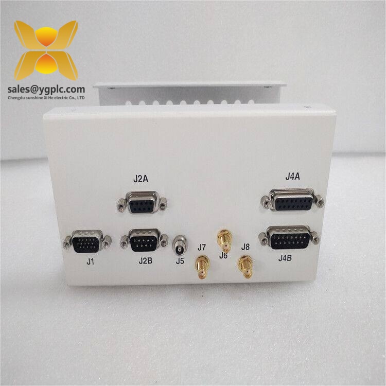
LAM 810-068158-014
Installation & Configuration Guide
Stage 1 — Pre-Installation Preparation
Estimated time: 10–15 minutes
⚠️ Safety first. Semiconductor equipment often combines high-voltage, RF, vacuum, pneumatic, and motion subsystems. Follow the equipment-specific LOTO procedure before touching the board.
- Notify the equipment owner and maintenance team.
- Put the tool into the approved maintenance state.
- Complete LOTO and electrical isolation according to the site procedure.
- Allow stored electrical energy to discharge according to the tool manufacturer’s procedure.
- Prepare:
- ESD wrist strap
- ESD mat
- Appropriate screwdrivers
- Calibrated multimeter
- Labels and marker
- Camera or phone
- Current equipment wiring/service documentation
- Record the existing board’s part number, revision, serial number, and visible configuration markings.
- Photograph the board, connectors, cable routing, and slot position.
Do not rely on memory. Photograph every connector before removal.
Stage 2 — Remove the Existing Board
Estimated time: 5–15 minutes
- Confirm the equipment is electrically isolated.
- Verify the board location against the equipment drawing.
- Label each connector before disconnection.
- Disconnect cables using the connector’s intended release mechanism.
- Do not pull directly on cable conductors.
- Release the board retaining hardware.
- Remove the PCBA carefully and place it immediately in an ESD-safe bag.
- Inspect the backplane or mating connectors for:
- Bent pins
- Contamination
- Oxidation
- Burn marks
- Mechanical damage
Keep the old board until the replacement has completed functional verification.
Stage 3 — Install 810-068158-014
Estimated time: 10 minutes
- Confirm the complete part number before installation.
- Compare the replacement board against the removed board.
- Check PCB revision and connector arrangement.
- Put on the ESD wrist strap.
- Remove the replacement from its static-shielding packaging.
- Align the board with the correct mounting position.
- Seat the connectors without excessive force.
- Reinstall retaining hardware.
- Restore every cable according to the photographs and equipment wiring diagram.
- Verify that no connector is partially seated.
Do not modify jumpers, switches, or board settings based on visual assumptions. Use the equipment-specific service documentation.
Stage 4 — Power-On and Functional Testing
Estimated time: 20–30 minutes
Before power-up:
- Inspect all connectors again.
- Confirm correct cable routing.
- Verify that no tools or loose hardware remain inside the equipment.
- Confirm the board is mechanically secured.
- Restore power according to the tool manufacturer’s sequence.
After power-up:
- Check equipment diagnostics.
- Confirm the controller recognizes the interface board.
- Check robot communication/status signals.
- Execute the approved robot initialization sequence.
- Verify home/reference status.
- Test representative robot commands.
- Confirm position, status, and interlock feedback.
- Check for communication or motion alarms.
- Run the applicable equipment self-test.
- Record the replacement board serial number in the maintenance log.
If the tool supports a service-mode diagnostic screen, capture the diagnostic status before and after replacement.
Stage 5 — Final QC and Spare Inventory Handling
Estimated time: 10 minutes
For incoming spare inventory:
- Verify supplier traceability and purchase documentation.
- Check the exact part number.
- Inspect the PCB for corrosion, scratches, rework marks, contamination, and damaged connectors.
- Record serial number and revision.
- Photograph the board before storage.
- Perform functional testing where an approved LAM test environment is available.
- Generate a Test Report.
- Seal the board in ESD-safe packaging.
- Add protective packaging suitable for PCB storage.
- Mark the inventory record with condition, test date, and warranty status.
A supplier listing currently describes this part as available in factory-sealed condition with a 12-month supplier warranty, while another listing offers new/used stock. These are seller-specific claims, not proof of original manufacturer status.
Technical Pitfalls — What Experienced Engineers Check
1. ❗ Part Number Looks Right, Revision Is Wrong
This is a classic spare-parts trap.
Two boards can share the same base part number while having different revision markings or equipment compatibility. Before installation, record the old board revision and compare it with the replacement.
Rule: Match the complete identification, not just the first few characters.
2. ❗ Connector Compatibility Is Not Enough
A connector can physically fit and still be associated with different signal assignments.
One field mistake can result in a robot interlock fault, failed initialization, or incorrect status feedback.
Take photos. Then check the wiring diagram.
3. ❗ ESD Damage
A PCBA does not need visible damage to have suffered an ESD event.
Use:
- Grounded ESD wrist strap
- ESD mat
- Static-shielding bag
- Controlled handling of connector pins
This is especially important when handling a spare that may have been stored for several years.
4. ❗ Do Not Trust Conflicting Online Specifications
This part is a good example.
One public listing describes it as a Node Robot Interface Board, while other sellers classify the same part number as a high-precision interface board, motion-control board, or even an RF-related assembly. The published voltage, dimensions, weight, and functional descriptions also conflict.
Procurement lesson: The physical nameplate and equipment documentation take priority over generic web listings.
5. ❗ Storage Conditions Matter
For long-term spare storage, keep the PCB:
- Inside ESD-safe packaging
- Protected from moisture
- Away from conductive contamination
- Clearly identified by part number and revision
- Recorded in the inventory system with storage date
For a high-value semiconductor-tool spare, capital tied up in an unverified board is worse than having a slightly larger buffer of verified stock.
Inventory Recommendation
For a critical LAM tool, I would classify 810-068158-014 as a low-frequency / potentially high-impact spare.
| Inventory Scenario | Suggested Min | Suggested Max | Strategy |
|---|---|---|---|
| One critical tool, no backup | 1 | 2 | On-site buffer stock |
| Several identical tools | 1 | 2 | Shared site inventory |
| Multiple fabs using same verified revision | 1 | 3 | Regional pool |
| Low-criticality application | 0 | 1 | Supplier-held stock |
| EOL or difficult sourcing | 1 | 3 | Lifecycle review + Last-time-buy |
Do not simply increase quantities. First check annual consumption, supplier lead time, repair turnaround, equipment downtime cost, and revision obsolescence risk.
For this type of semiconductor-equipment PCB, vendor consolidation plus one verified emergency spare can be more economical than maintaining several untested boards from different sources.
Frequently Asked Questions (FAQ)
1. What is LAM 810-068158-014?
Current supplier references identify it as a Node Robot Interface Board for LAM Research semiconductor equipment. Its role is associated with communication and signal interfacing between the equipment control architecture and robot/wafer-handling functions.
2. Is 810-068158-014 a PLC or standard industrial I/O module?
No evidence found supports treating it as a standard PLC module. Public listings consistently place it in the category of an equipment-specific PCB/interface board.
That distinction matters when sourcing replacements: do not substitute a generic PLC interface based only on voltage or connector similarity.
3. Can I directly replace my existing board with this part?
Potentially, if the complete part number, revision, equipment configuration, connector arrangement, and software environment match.
Before purchase, request a clear photo of the actual board and nameplate. That simple step can prevent an expensive mismatch.
4. Is this part new or refurbished?
Both conditions appear in the current supplier market. One seller advertises factory-sealed parts, while another listing explicitly offers new/used stock.
Ask the supplier to state the condition on the quotation and provide serial-number and physical-condition evidence.
5. Can the board be tested before shipment?
Yes, if the supplier has an appropriate LAM test setup. A meaningful report should identify the board’s part number, revision, serial number, test environment, diagnostic result, and test date.
A generic power-on statement is much less useful than an equipment-level functional test.
6. Why are the online specifications inconsistent?
Because third-party sellers appear to be using different descriptions for the same part number. Published data includes conflicting claims for voltage, frequency, dimensions, weight, and even functional classification.
For engineering procurement, treat unverified web specifications as reference data only. The actual board label, equipment documentation, and approved service information should control.
7. Should a fab keep one in buffer stock?
For a critical tool, usually yes.
A practical starting point is Min 1 / Max 2, then adjust according to failure history, supplier lead time, repair turnaround, and whether another site has the same verified revision available. That gives the maintenance team an insurance policy without turning slow-moving electronics into excessive inventory.