中文版
中文版

 Phone:
  Email:
  WhatsApp:
 Description
- Model: 810-048219-015
- Brand: Lam Research
- Series: Lam Research Semiconductor Equipment
- Core Function: Pulse signal sample-and-hold with sync output
- Type: PCB Assembly / Control Board
- Key Specs: Pulse sample and hold; synchronization output; semiconductor equipment interface
- Assembly Description: PCB ASSY, PULSE SMPL & HOLD W/ SYNC OUT
- Application: Lam Research semiconductor processing equipment
- Related Part Numbers: 810-048219-004, 810-048219-008
- Condition: Verify New Original, New Surplus, or Used before purchase
- Stocking Recommendation: Min 1 / Max 2 for critical equipment
Available parts records specifically identify 810-048219-015 as a Lam Research PCB assembly for Pulse Sample & Hold with Sync Out.
Product Introduction
Lam Research 810-048219-015 is a PCB assembly identified for Pulse Sample & Hold with Sync Out functions in semiconductor manufacturing equipment. It is an equipment-level control board rather than a generic industrial PLC card, so the exact tool configuration should be confirmed before replacement.
For spare-parts planning, this board belongs in the critical-tool inventory category when its failure can stop a process module. Public listings also associate nearby 810-048219 variants with pulse power sample-and-hold assemblies, but the exact suffix should be matched against the installed board before ordering.
Key Technical Specifications
| Parameter | Specification |
|---|---|
| Manufacturer | Lam Research |
| Model / Part Number | 810-048219-015 |
| Product Type | PCB Assembly |
| Board Description | Pulse Sample & Hold with Sync Out |
| Primary Function | Pulse signal sampling and holding |
| Output Function | Synchronization output |
| Equipment Category | Semiconductor manufacturing equipment |
| Application | Lam Research process equipment |
| Assembly Family | 810-048219 series |
| Related Variant | 810-048219-008 |
| Related Assembly | 810-048219-004 |
| Mounting / Interface | Equipment-specific; verify installed configuration |
| Operating Voltage | Not publicly verified |
| Operating Temperature | Not publicly verified |
| Dimensions | Not publicly verified |
| Weight | One aftermarket listing reports approximately 0.25 kg; verify actual shipping weight |
Important: Publicly available records provide the board function and identification, but do not establish reliable electrical ratings such as supply voltage, temperature range, connector pinout, or timing specifications. Those values should be taken from the applicable Lam Research equipment documentation or board revision.
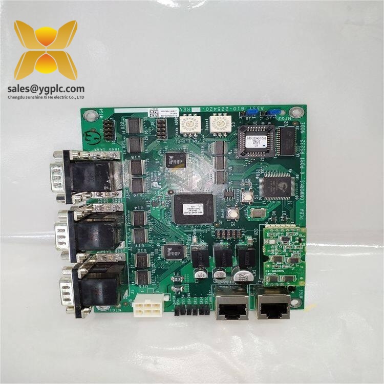
LAM 810-048219-015
Installation & Configuration Guide
Estimated engineering time: 30 minutes, assuming the replacement has already been identified and the equipment is accessible under an approved maintenance procedure.
Phase 1: Pre-Installation — 10 minutes
⚠️ Follow the semiconductor tool manufacturer’s maintenance procedure and site LOTO requirements.
- Notify the equipment owner and production team.
- Place the Lam Research tool in the approved maintenance state.
- Complete required wafer/process isolation procedures.
- Remove power according to the tool-specific procedure.
- Confirm that stored electrical energy has been discharged as specified by the equipment manual.
- Wear an ESD wrist strap and use an ESD-safe work surface.
Before removing the board, photograph:
- Complete part-number label
- Revision marking
- Connector locations
- Cable orientation
- Board position
- Nearby boards
- Jumper or switch settings, if present
Record the installed board serial number where applicable.
Phase 2: Remove Existing PCB — 5 minutes
- Verify that the equipment is in the required maintenance state.
- Label every cable or connector before removal.
- Disconnect connectors using their locking mechanism.
- Remove mounting screws or retaining hardware.
- Lift the PCB vertically and avoid contact with exposed components.
- Place the removed board in an ESD-safe bag.
Inspect the mating connectors.
A damaged connector can produce the same symptoms as a failed PCB, so do not throw the old board into scrap immediately.
Phase 3: Install Replacement PCB — 5 minutes
- Verify 810-048219-015 against the removed board.
- Check revision and assembly markings.
- Confirm connector keying.
- Install the PCB in the original mounting position.
- Secure all retaining hardware.
- Reconnect cables according to the photographs and equipment wiring documentation.
- Check every connector for full engagement.
Do not force a connector.
If the connector does not align naturally, stop and recheck orientation.
Phase 4: Power-On & Functional Test — 10+ minutes
- Perform a final visual inspection.
- Confirm that no tools or loose hardware remain inside the equipment.
- Restore power according to the approved procedure.
- Check equipment diagnostics.
- Verify board recognition where the tool controller provides hardware diagnostics.
- Confirm the pulse sample/hold function.
- Verify the synchronization output.
- Review process-tool alarms and interlocks.
- Run the equipment’s approved qualification or verification routine.
- Record the replacement date, board revision, serial number, and test result.
Do not bypass equipment interlocks simply to test the replacement PCB.
Quality Inspection & Test Process
1. Inbound Inspection
- Verify supplier traceability.
- Confirm full part number.
- Record revision and serial number.
- Inspect the PCB for corrosion, oxidation, cracked components, or repair marks.
- Check connectors for bent or damaged contacts.
- Compare the physical layout with the reference unit.
2. Live Functional Test
Use an appropriate Lam Research equipment test environment where available.
Test the board according to the applicable equipment procedure:
- Power-up behavior
- Board recognition
- Pulse sample function
- Hold function
- Synchronization output
- Controller communication
- Alarm/interlock response
Generate a Test Report.
A generic PLC test rack is not automatically suitable for this PCB. The board’s actual behavior depends on the Lam Research equipment architecture.
3. Electrical Inspection
Check, where permitted by the manufacturer’s procedure:
- Supply rails
- Ground continuity
- Connector continuity
- Abnormal resistance or short circuits
- Visible component damage
Avoid applying arbitrary hipot or insulation tests to populated semiconductor-equipment PCBs unless the manufacturer specifies them. The wrong test voltage can damage sensitive circuitry.
4. Revision Verification
Record:
- Part number
- Board revision
- Serial number
- Firmware or programmable-device revision, if applicable
- Configuration/jumper settings
This information should remain attached to the inventory record.
5. Final QC & Packaging
- QC inspector sign-off
- ESD bag
- Anti-static protection
- Bubble wrap
- Rigid carton
- QC Passed label
- Inspection date
For customer shipments, provide actual board photographs when requested.
Technical Replacement Risks
1. Wrong 810-048219 Variant
This is the first thing to check.
The 810-048219 family includes several related assemblies. Public records identify:
- 810-048219-004: Pulse Power Sample and Hold Assembly
- 810-048219-008: Pulse PRP Sample-Hold PCB
- 810-048219-015: PCB Assembly, Pulse Sample & Hold with Sync Out
They should not be treated as interchangeable simply because the base number is similar.
2. Revision Mismatch
A replacement with the correct base part number may still have a different board revision.
Before ordering:
- Photograph the installed board.
- Record every revision marking.
- Send the information to the supplier.
- Request a photograph of the replacement label.
- Confirm compatibility with the exact Lam Research tool configuration.
This takes minutes. A wrong board can cost a much longer troubleshooting session.
3. Connector or Cable Error
The board’s signal connections are equipment-specific.
Do not rely on memory.
Photograph the third connector from the left, not just the whole board. Close-up evidence is much easier to use during reinstallation.
4. ESD Damage
Semiconductor equipment boards deserve stricter handling than ordinary industrial control cards.
Use:
- ESD wrist strap
- Grounded ESD mat
- Anti-static packaging
- ESD-safe work area
Never place the PCB directly on a metal cabinet surface.
5. Incorrect Functional Test
A visual inspection does not prove that the pulse sample-and-hold and synchronization functions work.
Where possible, test the board in the actual compatible Lam Research tool or an approved equivalent test environment.
Inventory & Total Cost of Ownership
This is a classic slow-moving, high-impact spare.
A reasonable starting policy is:
| Equipment Situation | Min | Max | Stocking Strategy |
|---|---|---|---|
| One critical Lam tool | 1 | 1 | On-site buffer stock |
| Multiple identical tools | 1 | 2 | Central spare pool |
| Low-criticality application | 0 | 1 | Vendor-held stock |
| Long procurement lead time | 1 | 2 | Strategic buffer |
| EOL / difficult-to-source tool | 1 | 2+ | Last-time-buy assessment |
One aftermarket listing currently identifies the exact part as pre-owned, untested, and sold as-is, while another listing offers it as a circuit-board module with New/Used condition options. That spread is a good reminder: condition and test status should be treated as procurement fields, not sales adjectives.
For critical semiconductor equipment, the carrying cost of one tested spare is often easier to justify than emergency sourcing after a process interruption. Vendor consolidation also helps: keep approved suppliers for this legacy board and maintain at least one supplier capable of functional testing.
Frequently Asked Questions
1. What is LAM 810-048219-015 used for?
It is identified as a PCB assembly for Pulse Sample & Hold with Sync Out in Lam Research semiconductor equipment.
The exact equipment model should be confirmed before purchase.
2. Is 810-048219-015 the same as 810-048219-008?
No confirmed interchangeability should be assumed.
Both appear in the same 810-048219 family, but supplier records describe them differently. Match the complete suffix and board revision against the installed unit.
3. Can I buy a used 810-048219-015?
Yes, aftermarket listings exist. One current listing reports pre-owned stock and explicitly states that its units are untested and sold as-is.
For a production-critical tool, I would favor a tested unit with documented inspection over the cheapest as-is board.
4. What should I check before ordering?
Use this five-point check:
- Full part number: 810-048219-015
- Board revision
- Physical connector arrangement
- Exact Lam Research tool/model
- Condition and functional-test status
Ask for actual photographs. Stock photos are not enough for legacy PCB procurement.
5. Does the board have a published 24 VDC input?
I could not verify a reliable public source establishing the board’s exact supply voltage. Do not assume 24 VDC from generic industrial-board specifications.
Use the applicable Lam Research equipment documentation or the installed board’s electrical documentation.
6. How should I stock this part?
For a critical tool, 1 tested unit as buffer stock is a sensible baseline. If several identical tools use the same board, hold 1–2 units in a shared spare pool rather than duplicating inventory at every location.
7. What if the replacement powers up but the tool still alarms?
Start with the evidence, not the PCB.
Check the board revision, connector seating, cable orientation, equipment diagnostics, pulse-sample function, and synchronization output. If those pass, investigate the upstream/downstream circuitry and tool configuration.
That approach avoids burning hours swapping boards that were never the real fault.