中文版
中文版

 Phone:
  Email:
  WhatsApp:
 Description
- Model: TK-FTEB01
- Brand: Honeywell
- Series: Experion PKS / Series A Chassis
- Core Function: Fault Tolerant Ethernet bridge for DCS communication
- Type: FTE Bridge / Ethernet Communication Module
- Key Specs: Honeywell FTE network; dual redundant Ethernet links; Series A chassis installation
Honeywell documentation identifies TC-FTEB01/TK-FTEB01 as the Fault Tolerant Ethernet Bridge used to communicate between the Honeywell FTE network, servers, C200 controllers, and FIM-only chassis. Only one FTE Bridge is permitted per C200 Controller or FIM-only chassis.
⚠️ Lifecycle note: Independent industrial-part listings identify TK-FTEB01 as discontinued by the manufacturer, so remaining-stock availability should be verified before a planned replacement program.
Product Introduction
Honeywell TK-FTEB01 is an FTE Bridge module for Honeywell Experion PKS control hardware. It provides the Ethernet communication path between the chassis and Honeywell’s Fault Tolerant Ethernet network, supporting critical communication involving controllers and supervisory systems. Honeywell hardware documentation lists the module for Series A chassis applications.
For maintenance teams, the important point is the network architecture rather than generic Ethernet speed. The module is associated with redundant FTE communication and dual network connections; product references identify 51309512-175 as the corresponding part number.
Key Technical Specifications
| Parameter | Specification |
|---|---|
| Manufacturer | Honeywell |
| Model | TK-FTEB01 |
| Part Number | 51309512-175 |
| Module Type | Fault Tolerant Ethernet Bridge |
| System Compatibility | Honeywell Experion PKS |
| Chassis | Series A chassis |
| Network | Honeywell Fault Tolerant Ethernet (FTE) |
| Ethernet Interface | Dual RJ45 redundant network connections |
| Installation | Chassis slot, backplane connection |
| Power Consumption | Published references list low-current DC requirements; exact revision-specific values should be verified against the applicable Honeywell manual |
| Operating Temperature | Some secondary listings specify -40°C to +70°C; verify the exact hardware revision before engineering release |
| Weight | Approximately 0.28–0.29 kg in several secondary listings |
Honeywell’s hardware planning documentation confirms the TC-FTEB01/TK-FTEB01 FTE Bridge function and its Series A chassis application. Secondary technical listings provide the 51309512-175 association and dual-network architecture, but revision-specific electrical and environmental values should be checked against the installed system documentation before procurement or replacement.
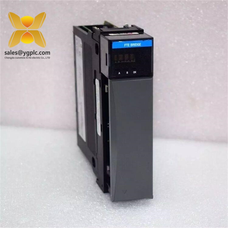
Honeywell TK-FTEB01
Installation & Configuration Guide
Stage 1 — Pre-Installation
Estimated time: 10–15 minutes
⚠️ Safety first.
- Notify the control-room and production team of the planned intervention.
- Confirm that the affected control system is in the required safe operating state.
- Follow the site’s approved shutdown or maintenance procedure before removing the module.
- Apply ESD protection before touching the module.
- Back up current configuration information.
Before handling the module, Honeywell installation guidance specifically calls for ESD precautions: discharge static potential, use an approved grounded wrist strap, avoid touching backplane connector pins and circuit components, and keep the module in its static-safe packaging when not installed.
Stage 2 — Record Existing Configuration
Estimated time: 5–10 minutes
Take clear photographs of:
- Existing module label and part number
- Device Index setting
- Cable connections
- Cable shield-ground jumper configuration
- Chassis slot position
- Ethernet Port A / Port B connections
Honeywell installation documentation specifically identifies Device Index, cable shield ground jumper, and MAC address as configuration items to check when installing the TK-FTEB01/TC-FTEB01.
Stage 3 — Remove the Existing Module
Estimated time: 5–10 minutes
- Confirm the approved maintenance state.
- Identify and label both Ethernet connections.
- Disconnect the FTE network cables carefully.
- Release the chassis retaining mechanism.
- Withdraw the module vertically from the chassis.
- Inspect the backplane connector for bent pins, contamination, or mechanical damage.
Do not touch the backplane connector pins. Honeywell explicitly warns that electrostatic discharge and improper handling can damage integrated circuits and semiconductor devices.
Stage 4 — Install the Replacement
Estimated time: 10 minutes
- Verify that the replacement is TK-FTEB01 / 51309512-175.
- Compare the replacement with the removed module.
- Set the required Device Index before installation.
- Verify the cable shield-ground jumper position against the existing configuration.
- Insert the module into the correct chassis position.
- Secure the module according to the chassis hardware procedure.
- Reconnect the redundant FTE network cables.
- Confirm that Port A and Port B are connected to the intended network paths.
Honeywell documentation describes the TK-FTEB01 as a pluggable FTE Bridge module and specifically includes installation of the module and attachment of FTE cables in the installation procedure.
Stage 5 — Power-Up and Verification
Estimated time: 10–20 minutes
- Confirm that all connections are mechanically secure.
- Restore power according to the site procedure.
- Check module status indications.
- Verify that the module is recognized by the Experion environment.
- Confirm the Device Index and MAC-related information.
- Check both redundant FTE communication paths.
- Verify controller and supervisory-system communication.
- Monitor the system for communication alarms.
Do not assume that a physically identical module is automatically configuration-identical. A wrong Device Index or incorrect network connection can prevent proper FTE operation even when the module itself is functional. Honeywell’s installation documentation specifically calls for Device Index and MAC-address checks.
Frequently Asked Questions
1. What is Honeywell TK-FTEB01 used for?
It is an FTE Bridge module used in Honeywell Experion control hardware. Its job is to provide the communication path between the chassis and Honeywell’s Fault Tolerant Ethernet network. Honeywell documentation lists communication between servers, C200 controllers, and FIM-only chassis among its applications.
2. Is TK-FTEB01 the same as 51309512-175?
Yes. Multiple industrial automation references identify 51309512-175 as the associated part number for TK-FTEB01.
3. Can I directly replace TC-FTEB01 with TK-FTEB01?
The two models are listed together by Honeywell as TC-FTEB01/TK-FTEB01 FTE Bridge variants. However, do not treat the replacement as a blind plug-in swap. Verify chassis compatibility, configuration, Device Index, wiring, and the applicable firmware/hardware revision before installation.
4. Does TK-FTEB01 use redundant Ethernet connections?
Yes. Technical references describe the module as an FTE Bridge with dual RJ45 network connections for redundant FTE communication. The two physical network paths should be checked carefully during replacement.
5. My system is already running. Can I remove the module while powered?
Do not assume that it is hot-swappable. The installation documentation treats module installation as a controlled maintenance operation and places strong emphasis on ESD handling and pre-installation checks. Follow the specific Experion hardware installation procedure and your site’s approved maintenance method before removing the module.
6. Is TK-FTEB01 still available as a new module?
Availability varies by supplier. At least one established industrial-part listing identifies the model as discontinued by the manufacturer, while other suppliers list new or surplus units. For a critical DCS spare, verify the exact condition, serial number, packaging, and warranty terms before purchase.
7. What should I check before ordering?
Send the supplier the complete model number, part number 51309512-175, existing chassis type, system platform, and current module photos. For an installed system, also record the Device Index and network configuration. That information reduces the chance of receiving a physically similar but configuration-inappropriate spare.
Inventory recommendation: Because independent references indicate that this module is discontinued, treat TK-FTEB01 as a lifecycle-controlled spare rather than a normal fast-moving item. For a critical Experion installation, maintaining 1–2 verified spare units can be reasonable when replacement lead time is uncertain; the final Min/Max level should be based on installed-base count, failure history, lead-time variability, and the cost of a process shutdown.