中文版
中文版

 Phone:
  Email:
  WhatsApp:
 Description
- Model: TC-PRR021
- Brand: Honeywell
- Series: Experion PKS C200
- Core Function: Supports redundant C200 controller operation
- Type: Redundancy Module (RM)
- Key Specs: 24 VDC; 90 mA; uses 2 chassis slots
- Part Number: 51309288-225 is a reported associated part number; verify the nameplate before ordering.
- Condition: Confirm actual condition before purchase: New Original, New Surplus, or Refurbished
- Stocking Recommendation: Min 1 unit / Max 2 units for a critical C200 redundancy application
⚠️ Lifecycle status: Multiple industrial automation distributors list TC-PRR021 as discontinued by the manufacturer. Treat remaining stock as lifecycle-sensitive and verify revision before purchase.
Product Introduction
Honeywell TC-PRR021 is a Redundancy Module for the Experion PKS C200 control system. It supports C200 controller redundancy and occupies 2 chassis slots, making it a key spare for systems where controller availability matters.
The electrical requirement is modest: 24 VDC with approximately 90 mA current consumption. Some listings associate the model with 51309288-225 and report a 0°C to 60°C operating range; revision and exact configuration should be checked against the original Honeywell documentation before replacement.
Key Technical Specifications
| Parameter | Specification |
|---|---|
| Manufacturer | Honeywell |
| Model | TC-PRR021 |
| Product Type | C200 Redundancy Module |
| System | Experion PKS C200 |
| Function | C200 controller redundancy |
| Supply Voltage | 24 VDC |
| Current Consumption | 90 mA at 24 VDC |
| Chassis Occupancy | 2 chassis slots |
| Product Family | Honeywell Experion PKS C200/C200E |
| Series Designation | TC series |
| Conformal Coating | TC series; verify exact hardware revision |
| Reported Operating Temperature | 0°C to 60°C |
| Reported Humidity | 5% to 95%, non-condensing |
| Reported Weight | Approximately 0.46 kg |
| Associated Part Number | 51309288-225 |
| Country of Origin | Reported as USA by some suppliers; verify actual unit documentation |
| Lifecycle | Reported discontinued by manufacturer |
Technical data above is compiled from available distributor and technical-document sources. Where supplier records conflict, the physical nameplate and applicable Honeywell manual should control.
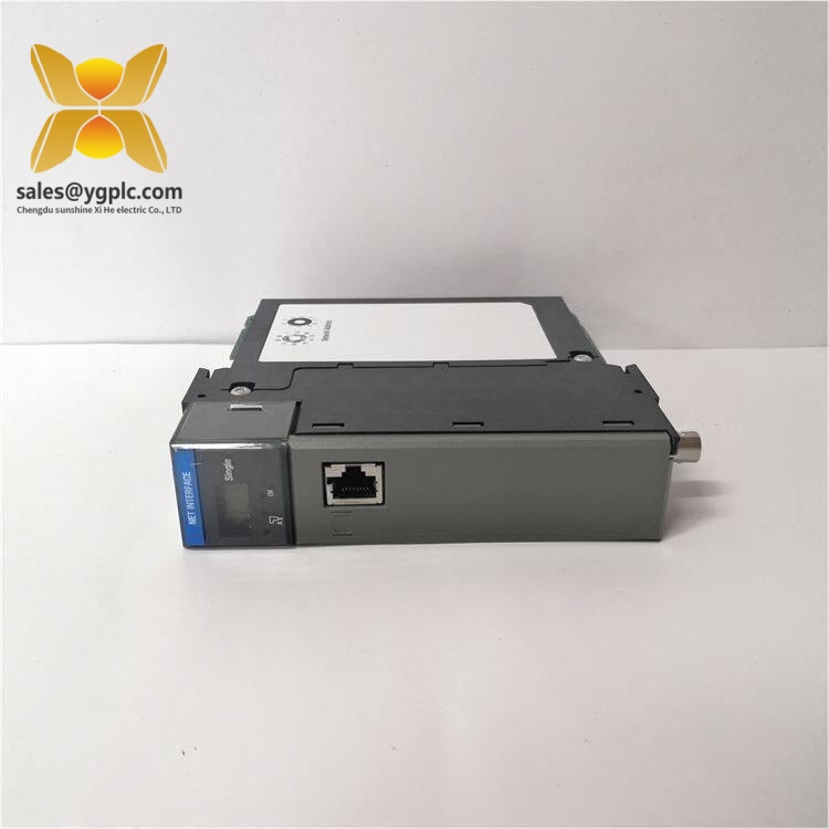
Honeywell TC-PRR021
Installation & Configuration Guide
Estimated replacement time: 25–30 minutes, excluding troubleshooting or firmware/configuration work.
Phase 1: Pre-Installation — 10 minutes
⚠️ Safety first.
- Notify the production team about the planned maintenance window.
- Place the process in a safe state. Stop motors, isolate relevant valves, and follow the site’s LOTO procedure.
- Disconnect control-system power, including UPS-fed circuits where applicable.
- Wait for the equipment-specific discharge period specified by the Honeywell documentation. Do not assume that 5 minutes is sufficient for every cabinet.
- Wear an ESD wrist strap and work on an ESD-safe surface.
Before touching the old module, photograph:
- Module nameplate and serial number
- Chassis position
- Connector locations
- Controller redundancy arrangement
- Any visible hardware or revision markings
- Existing wiring and cabinet layout
Back up the current C200 configuration before removal. Keep both a local copy and a controlled engineering-system copy.
Phase 2: Remove the Existing Module — 5 minutes
- Confirm the module position against the cabinet drawing.
- Verify that the replacement model and hardware revision are appropriate.
- Do not pull on cables or connectors.
- Release the module using the C200 chassis mechanism specified for the installed hardware.
- Withdraw the module carefully.
- Inspect the backplane connector for bent pins, contamination, oxidation, or mechanical damage.
Keep the old unit available until the replacement has passed functional testing.
Phase 3: Install the Replacement — 5 minutes
- Keep the replacement module inside its ESD packaging until installation.
- Verify the complete model number and revision.
- Compare the replacement with the removed unit.
- Align the module with the correct C200 chassis position.
- Engage the backplane connector without forcing the module.
- Secure the module according to the chassis procedure.
- Recheck connector seating and cabinet alignment.
Do not assume that a visually similar Honeywell module has identical hardware or firmware characteristics. The TC and TK families can have related functionality but different construction details; verify the exact configuration before substitution.
Phase 4: Power-On & Functional Test — 10 minutes+
Before energizing:
- Confirm all connections.
- Verify the cabinet power supply against the equipment specification.
- Check for visible shorts or loose conductors.
- Confirm the redundant-controller arrangement.
- Remove tools and temporary labels from the cabinet.
After power-up:
- Observe the module status indicators.
- Check the C200 controller diagnostic status.
- Confirm that the redundancy relationship is recognized.
- Check controller communication and system health.
- Verify that the primary and standby paths report the expected status.
- Review Experion diagnostics for active faults.
- Where the site procedure permits, perform a controlled redundancy/switchover test.
- Monitor the system for at least 30 minutes.
- Record the replacement date, serial number, revision, technician, and test result.
Do not force a controller switchover on a live process simply to prove the spare works. Use the site’s approved redundancy test procedure.
Quality Inspection & Test Process
For stocked TC-PRR021 units, a practical incoming inspection sequence is:
- Inbound inspection
- Verify supplier traceability and available packing documentation.
- Check serial number and nameplate.
- Inspect for corrosion, scratches, repair marks, discoloration, or aging.
- Confirm supplied documentation and accessories where applicable.
- Live functional test
- Use a compatible Honeywell C200 test environment where available.
- Perform power-up diagnostics.
- Verify redundancy-module recognition.
- Check controller redundancy status.
- Run the unit under controlled conditions for more than 24 hours when the inventory policy requires extended testing.
- Record results in a Test Report.
- Electrical checks
- Verify supply voltage.
- Check grounding continuity where applicable.
- Perform insulation or dielectric testing only when appropriate for the module and permitted by the manufacturer’s test procedure.
- Firmware and configuration verification
- Record firmware/hardware revision.
- Photograph relevant configuration information.
- Record the serial number against the inventory record.
- Final QC and packaging
- QC sign-off.
- ESD bag.
- Bubble wrap plus carton.
- QC Passed label with inspection date.
Test photographs and videos can be provided to the customer when available. That is more useful than simply stating that a module was “tested.”
Technical Replacement Risks
1. Firmware or Hardware Revision Mismatch
A replacement can have the correct model number but still require revision verification.
Avoid the problem:
- Record the existing module revision.
- Record the replacement revision before installation.
- Compare against the installed C200 configuration.
- Ask the supplier to confirm revision compatibility before shipment.
A small revision difference can become a long commissioning session. Well, technically the model may be correct, but the installed system configuration still matters.
2. Chassis Position Errors
TC-PRR021 is reported to consume 2 chassis slots.
Take a photo before removal.
That simple step prevents a surprising number of cabinet mistakes.
3. Connector and Backplane Damage
Never use excessive force when removing or installing the module.
Inspect the backplane carefully. A damaged connector can look like a failed replacement module after power-up.
4. Power-System Assumptions
The module is reported at approximately 90 mA from 24 VDC, but the complete C200 chassis load is what matters for power sizing.
Do not size the cabinet supply around this module alone. Include the controller, I/O, communication hardware, and other chassis loads.
5. ESD
Use an ESD wrist strap and grounded work surface.
Do not handle the PCB or connector contacts unnecessarily. A module that passes visual inspection can still suffer latent ESD damage.
Inventory & Total Cost of Ownership
For a critical C200 installation, keeping 1 spare TC-PRR021 on site is a sensible insurance position. If the plant has several identical C200 systems, a shared pool of 2 units can often cover multiple sites more efficiently than stocking one unit at every cabinet.
| Inventory Situation | Recommended Level | Reason |
|---|---|---|
| Single critical C200 system | Min 1 / Max 1 | Basic insurance spare |
| Multiple identical C200 systems | Min 1 / Max 2 | Cross-site sharing reduces capital tied up |
| Long lead-time site | Min 1 / Max 2 | Covers supply uncertainty |
| Non-critical application | Vendor stock / consignment | Avoid idle capital |
| Confirmed EOL exposure | Strategic last-time-buy | Protect against future scarcity |
Because TC-PRR021 is reported as discontinued, lifecycle risk is more important than normal consumption rate.
A $2,000 spare may look expensive on the inventory report. Compared with an unplanned C200 controller outage, however, the total cost can be very different. Carrying cost, obsolescence risk, emergency freight, and production loss should all enter the TCO calculation.
Frequently Asked Questions
1. What is Honeywell TC-PRR021 used for?
It is a C200 Redundancy Module used to support controller redundancy in the Honeywell Experion PKS C200 architecture. It occupies 2 chassis slots.
2. Is TC-PRR021 still manufactured?
Multiple industrial automation suppliers currently identify the part as discontinued by the manufacturer. Availability therefore depends on surplus and aftermarket inventory.
For a plant still running C200 hardware, this is a good candidate for a lifecycle review and last-time-buy assessment.
3. My system uses a C200. Can I replace TC-PRR021 directly?
Do not assume direct replacement from the model number alone.
Check these three items:
- Existing module part number and revision.
- C200 chassis configuration.
- Applicable Honeywell documentation and system revision.
If the spare has a different hardware or firmware revision, confirm compatibility before installation.
4. Does TC-PRR021 require 24 VDC?
Yes. Available technical records report 24 VDC operation with approximately 90 mA current consumption.
The cabinet power budget still needs to be calculated at system level.
5. Can I install it while the C200 system is running?
Do not treat it as a generic hot-swap module.
Whether a live replacement is permitted depends on the specific C200 architecture, chassis configuration, process state, and approved maintenance procedure. For a production system, follow the Honeywell documentation and site LOTO/MOC procedure rather than assuming hot replacement is safe.
6. How do I verify that the spare is genuine and suitable?
Ask for:
- Clear nameplate photographs
- Full model and part number
- Hardware/firmware revision
- Serial number
- Condition statement
- Test report
- Packaging photographs
- Warranty terms
For a discontinued module, revision traceability is particularly important. A low-priced unit with unclear history can create more TCO than a properly documented spare.
7. What should I stock for a critical C200 system?
For one critical installation, 1 tested spare is the practical minimum. If several C200 systems share the same configuration, holding 2 units centrally can provide better capital efficiency while preserving emergency coverage.
For slow-moving discontinued hardware, vendor-managed or consignment stock is also worth discussing where available.