中文版
中文版

 Phone:
  Email:
  WhatsApp:
 Description
- Model: 51309512-175C
- Brand: Honeywell
- Series: Experion PKS / Series-A Chassis
- Core Function: Bridges controller traffic to the FTE network
- Type: Fault Tolerant Ethernet (FTE) Bridge Module
- Key Specs: Dual Ethernet ports; IEEE 802.3; 24 VDC-class supply
- Common Hardware: TK-FTEB01, revision-dependent
- Compatibility: Experion PKS / Experion LS Series-A architecture
Product Introduction
The HONEYWELL 51309512-175C is associated with the TK-FTEB01 Fault Tolerant Ethernet (FTE) Bridge Module used in Honeywell Experion PKS and Experion LS systems. The underlying part number 51309512-175 is identified by multiple industrial automation references as an FTE bridge that connects Series-A chassis hardware to Honeywell’s fault-tolerant Ethernet architecture.
For an MRO replacement, revision matters. Some supplier records identify the base 51309512-175 as TK-FTEB01 and separately list revision C hardware, while others use the full suffix directly. The module is reported with dual RJ-45 network interfaces, 24 VDC-class control power, and Series-A chassis mounting. That means the original label, hardware revision, chassis type, and network configuration should be checked together before purchase.
Key Technical Specifications
| Parameter | Specification |
|---|---|
| Model | 51309512-175C |
| Manufacturer | Honeywell |
| Product Family | Experion PKS / Experion LS |
| Product Type | Fault Tolerant Ethernet Bridge Module |
| Associated Model | TK-FTEB01 |
| Hardware Platform | Series-A Chassis |
| Network Standard | IEEE 802.3 Ethernet |
| Ethernet Interfaces | 2 × RJ-45 reported for redundant links |
| Supply | 24 VDC-class control supply |
| Typical Input Range | 18–30 VDC reported by supplier documentation |
| Power Consumption | Approx. 1.5 W nominal, source-dependent |
| Isolation | Up to 1,000 VDC reported |
| Mounting | Series-A chassis slot |
| Operating Temperature | -40 to +70°C reported by secondary references |
| Typical Application | Experion PKS FTE network communication |
| Revision | C |
The base 51309512-175 is consistently identified as an FTE bridge module, while current supplier records specifically list a revision C version. Exact electrical limits should be confirmed against the hardware revision and Honeywell documentation supplied with the installed system.
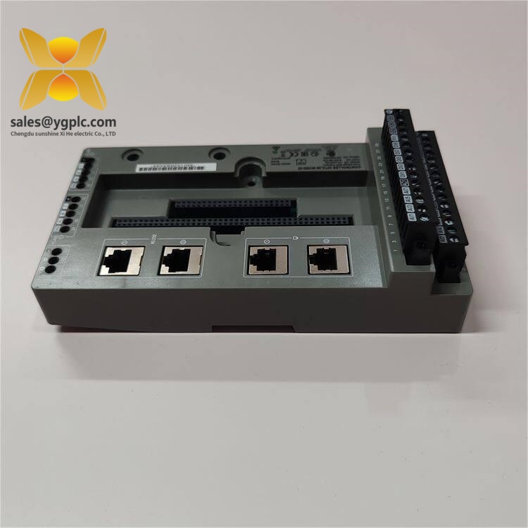
HONEYWELL 51309512-175C
Key Features and Practical Value
- Dual network connectivity for fault-tolerant Ethernet architectures.
- Designed for Honeywell Series-A chassis installation.
- Interfaces controller-side traffic with the Experion FTE network.
- Supports redundant communication paths in applicable configurations.
- Compact plug-in construction simplifies replacement of installed hardware.
- Suitable for legacy Experion PKS and Experion LS maintenance programs.
- A useful spare where a failed FTE bridge could interrupt controller communications.
This is a network-interface component, not an ordinary Ethernet switch. The Honeywell FTE architecture and chassis integration are the important parts.
Typical Applications
The module is typically associated with Honeywell process-control infrastructure, including:
- Experion PKS controller networks
- Experion LS installations
- Distributed control system (DCS) communication
- Series-A controller chassis
- Redundant industrial Ethernet networks
- Legacy process-plant automation cabinets
For plant maintenance, it is most useful where the existing FTE network is still in service. Replacing it with a generic managed switch would not reproduce the same chassis-level function.
Related Models
TK-FTEB01 — The Honeywell model designation commonly associated with part number 51309512-175. Supplier records identify it as an FTE Bridge Module for Series-A chassis.
TC-FTEB01 — Alternate designation appearing in aftermarket catalogs for the same base part-number family. The exact hardware revision should be matched before interchange.
51309512-175 — Base Honeywell part number from which revision-specific units such as 51309512-175C are identified in supplier records.
Series-A Chassis — Honeywell chassis platform associated with this FTE bridge architecture.
Installation and Maintenance
Before replacement, record the hardware revision, device index, chassis slot, network cable positions, and controller configuration. Take clear photographs before disconnecting anything.
The BCD rotary switch or device-index setting should be checked against the removed module where applicable. Some supplier technical guidance also notes that cable-shield grounding jumpers and device-index settings need to match the original installation. After power restoration, the module may receive network configuration through Honeywell services such as BOOTP, depending on the system design.
After installation, verify both Ethernet links, FTE communication status, controller connectivity, diagnostics, and network redundancy. Do not return a critical process controller to normal operation until communication has been checked from the actual Experion workstation or engineering environment.
Quality Inspection and Test Procedure
For New Original, New Surplus, used, or refurbished stock, the inspection should be traceable.
1. Inbound inspection
- Verify part number and revision.
- Check serial number and nameplate.
- Inspect RJ-45 connectors, chassis fingers, housing, and labels.
- Look for corrosion, impact marks, overheating, or repair evidence.
- Verify supplied documentation and accessories.
2. Live Test
Use a compatible Honeywell Experion Series-A / FTE test environment.
- Power-up check
- Link-status verification
- FTE communication handshake
- Redundant Ethernet path check
- Controller-to-network communication test
- Extended powered operation where practical
- Generate a Test Report
3. Electrical Testing
Verify the applicable DC supply and grounding conditions. Insulation or withstand testing should only be performed where authorized by the applicable Honeywell procedure.
4. Firmware and Configuration Verification
Record the hardware revision and available firmware/image information. Preserve device-index and grounding-jumper settings with photographs.
5. Final QC
After QC approval, package the module in antistatic protection with shock-resistant cushioning and a rigid carton. Attach the QC status and inspection date. Test photos or video can be supplied with the shipment record.
Technical Replacement Pitfalls
Revision mismatch: The base number may be identical while the suffix identifies a different hardware revision. Match the full 51309512-175C designation.
Wrong device index: A replacement with the wrong rotary-switch setting can prevent normal network integration. Photograph the old setting first.
Network-cable mix-up: Dual Ethernet links are part of the fault-tolerant architecture. Label both cables before removal.
Grounding configuration: Check the cable-shield grounding arrangement. A change here can create communication or EMC problems.
Firmware/image mismatch: Record the existing image or firmware revision where accessible. Do not assume a newer spare is automatically correct.
ESD: Use an antistatic wrist strap and ESD-safe work surface during handling. The connector and board electronics should never be handled casually.
Procurement Guidance
For international MRO purchasing, specify the full identification as Honeywell 51309512-175C / TK-FTEB01, then state the condition, hardware revision, test status, warranty, country of origin, lead time, and Incoterms.
For customs documents, a clear description such as “industrial DCS Fault Tolerant Ethernet bridge module” is preferable to a generic phrase such as “electronic board.” Final HS classification should be confirmed for the actual shipment and destination country.
Do not quote the base part number alone when the installed system specifically requires revision C. That small suffix can be the difference between a correct spare and a cabinet-side troubleshooting session.
Quick Conclusion
- 51309512-175C is a revision-specific Honeywell FTE bridge module associated with TK-FTEB01.
- It is designed for Experion PKS / Experion LS Series-A network architectures.
- Dual Ethernet connectivity supports the applicable fault-tolerant network arrangement.
- Hardware revision, device index, cable routing, and FTE configuration should be verified before replacement.
- For critical MRO procurement, purchase against the complete revision-specific part number, not only the 51309512-175 base number.