中文版
中文版

 Phone:
  Email:
  WhatsApp:
 Description
- GE VMIVME-7697-160 | Pentium III Embedded SBC with Flash Storage & VME64 Support
Product Core Brief
- Model: GE VMIVME-7697-160
- Brand: GE (Former VMIC)
- Series: VMIVME VMEbus Single Board Computer Series
- Core Function: PC/AT-compatible 6U dual-slot VME CPU for embedded industrial multiprocessing control
- Type: VME Single Board Computer (SBC / Controller Card)
- Key Specs: Pentium III CPU | 100MHz System Bus | VME64 Master/Slave | Onboard Flash Storage
- Condition: New Original Surplus, No Refurbishment, Full Factory Functionality Verified
- Status: ⚠️ Discontinued OEM production, limited inventory available
Key Technical Specifications
| Parameter Item | Specification Value |
|---|---|
| Full Part Number | VMIVME-7697-160 |
| Form Factor | Dual-slot 6U VMEbus Eurocard, 160 × 233.25 × 20.32 mm |
| Main Processor | Intel Pentium III (factory fixed speed for -160 variant) |
| System Bus Clock | 100 MHz |
| Main Memory | Up to 512 MB 144-pin SODIMM SDRAM |
| Non-Volatile Storage | 8–192 MB bootable secondary IDE flash disk |
| Backup Memory | 128 KB battery-backed SRAM (NVRAM) |
| VMEbus Compliance | VME Rev C.1, VME64; A16/A24/A32, D08/D16/D32, BLT32, MBLT64 |
| Onboard Graphics | 64-bit AGP SVGA, 4 MB SGRAM, max 1600×1200 resolution |
| Network Interface | 10/100BaseTX Fast Ethernet (RJ45 front panel) |
| Serial Ports | 2× 16550-compatible RS232 serial channels |
| Aux I/O | ECP/EPP parallel port, PS/2 keyboard/mouse, USB 1.1, IDE/Floppy via P2 connector |
| Timing Hardware | 3× programmable 32-bit timers + 16-bit watchdog timer (1ms resolution) |
| Operating Temp | 5 °C ~ +50 °C (indoor rack only) |
| Storage Temp | -25 °C ~ +60 °C |
| Power Draw | Powered via VMEbus P1 connector, typical 18–22 W under full load |
| MTBF | > 50,000 hours under rated operating conditions |
Product Introduction
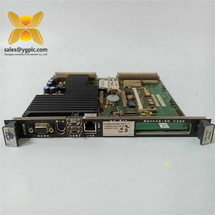
GE VMIVME-7697-160
Application Scenarios & Pain Points
Typical Application Scenarios
- Power Plant Auxiliary Monitoring & Control
Rack-mounted VME control for turbine lube systems, flue gas emission analyzers and boiler feedwater regulation. The long-lifecycle Pentium III architecture runs legacy Windows NT industrial SCADA software that cannot migrate to x86_64 hardware.
- Defense & Aerospace Test Benches
Hardware-in-the-loop (HIL) simulation racks for avionics component validation. VME64 block transfer modes deliver low-latency sensor data acquisition required for real-time flight model calculations.
- Metallurgy Continuous Casting Line Control
Distributed multiprocessor VME systems tracking furnace temperature, rolling speed and slab positioning. Battery-backed SRAM retains critical production setpoints during brief power interruptions.
- Nuclear Plant Balance-of-Plant Monitoring
Safety-related secondary circuit data logging and interlock logic. Legacy regulatory validation documents are tied exclusively to VMIVME-7697 series hardware, prohibiting full platform replacement.
- Scientific Research Signal Acquisition
Laboratory multi-channel DAQ racks paired with VME analog input/output modules. Onboard dual serial ports connect to external precision calibration instruments.
Real Engineering Case
Compatibility & Replacement Matrix
- GE VMIVME-7697-160 → GE VMIVME-7697-850 : Partial compatible, CPU clock speed mismatch requires BIOS reconfiguration, must re-test VME interrupt mapping
- GE VMIVME-7697-160 → GE VMIVME-7697-550 : Partial compatible, identical mechanical pinout; flash storage capacity differs, OS boot partition resizing mandatory
- GE VMIVME-7697-160 → GE VMIVME-7697 base model (no suffix): Conditional replacement, system bus timing register values differ, risk of VME data corruption without software adjustment
- GE VMIVME-7697-160 → VMIVME-7750 series VME SBC : Not directly compatible, different VME bridge chipset, full control software rewrite required
- GE VMIVME-7697-160 → Matching OEM VMIVME-7697-160 : Direct drop-in replacement, identical jumper layout, bus timing and memory mapping; no wiring or software modification needed
SOP Quality Transparent Inspection Flow
- Warehouse Receiving Inspection
Trace product origin via original VMIC/GE factory packing slip and import customs documentation; scan serial number against manufacturer database to verify genuine OEM part. Full visual inspection checklist: no PCB corrosion, no front-panel connector bending, no repair solder marks, no yellowed aging plastic, intact original shielding housing. Cross-check complete accessory kit: hardware user manual, factory test certificate, spare terminal jumpers.
- Live Rack Function Test
Test bench built with standard 21-slot VME chassis and matching peripheral I/O cards for full simulation testing. Execution sequence: power-on POST indicator validation, watchdog timer timeout test, dual RS232 serial communication loopback, 10/100 Ethernet throughput stress test, full VME64 BLT/MBLT block transfer cycle, continuous 24-hour runtime load test with temperature rise logging. A signed digital test report is generated after all steps; test photos and runtime video can be shared with buyers upon request.
- Electrical Parameter Detection
500 V megohmmeter insulation resistance test between PCB traces and chassis ground, continuity check for all VME P1/P2 pins, withstand voltage isolation test per GE factory specifications.
- Firmware & Hardware Configuration Record
Read and log factory BIOS firmware revision number; capture high-resolution photos of all onboard DIP switches, VME bus jumpers and flash storage configuration for permanent backup files.
- Final QC & Packing
Certified inspector signs off all test records; board sealed inside anti-static shielding bag, wrapped with shock-absorbent bubble film and placed into rigid shockproof carton. Outer packaging affixed with QC Passed sticker printed with full serial number and inspection date.
On-site Replacement Risk Avoidance Guide
1. Firmware / BIOS Version Mismatch Risk
Avoidance Steps: Record BIOS version string displayed during old board power-on POST before disassembly; specify matching BIOS revision range during purchasing. If version discrepancy exists, we can perform BIOS re-flashing before delivery.
Real Case: A metallurgy engineer installed a mismatched VMIVME-7697 variant without checking BIOS; the control rack randomly lost communication with analog I/O modules for three full shifts until BIOS alignment was completed.
2. Jumper & DIP Switch Configuration Misalignment Risk
Avoidance Steps: Capture clear close-up photos of every jumper bank and DIP switch bank on the faulty SBC before removal; replicate all physical settings on the new board before rack insertion. Critical reminder: VMEbus system controller slot (slot 1) requires unique termination jumpers not used on expansion CPU slots.
Key Reminder: This low-level configuration error accounts for over 60% of post-replacement VME communication faults. Always photograph all hardware jumpers.
3. P2 Expansion Connector Wiring Mismatch Risk
Avoidance Steps: Extract and archive the original project wiring diagram before swapping hardware; cross-reference P2 pin definitions in the VMIVME-7697 technical manual before connecting peripheral storage devices.
Warning Note: Do not reuse existing P2 ribbon cables without pinout validation; different production batches of VMIVME-7697 can carry minor P2 signal layout differences.
4. Chassis Power Load Overdraw Risk
Avoidance Steps: Calculate aggregate power draw of all installed modules, reserve minimum 20% headroom above supply nominal rating. If total load exceeds limits, upgrade rack power unit or add secondary auxiliary power module.
Reference Data: Single VMIVME-7697-160 draws approximately 20 W under full processing load; four such SBCs in one chassis consume ~80 W combined.
5. ESD Static Component Damage Risk
Avoidance Steps: Mandate certified anti-static wrist strap and conductive anti-static mat during all board handling; avoid direct finger contact with PCB gold contact fingers, flash memory chips and serial port transceivers.
Field Lesson: A maintenance technician skipped ESD protection during a weekend repair; the replacement VMIVME-7697-160 failed Ethernet communication permanently after first power-up, requiring a second emergency spare shipment and 8 hours of lost production.