中文版
中文版

 Phone:
  Email:
  WhatsApp:
 Description
- GE VLC-853-E | VersaMax Local Control Module, Authorized Surplus Inventory
Product Core Brief
- Model: VLC-853-E
- Brand: GE Automation & Controls
- Series: VersaMax Micro / VersaMax Local Controller System
- Core Function: Standalone local logic controller for distributed field I/O sub-stations
- Condition: New Original Surplus, No Refurbishment Marks
- Type: Local Controller Module (Sub-CPU Unit)
- Key Specs: 16 integrated digital I/O | RS485 serial bus | 24 VDC operating supply
- Note: ⚠️ Base series production discontinued, limited stock available
Key Technical Specifications
| Parameter Item | Technical Value |
|---|---|
| Full Part Number | VLC-853-E |
| Power Supply Input | 24 VDC ±10% |
| Integrated Digital I/O Count | 8 Digital Inputs + 8 Digital Outputs (16 total) |
| Field Communication Port | RS485, GE Genius Bus Protocol |
| Local Logic Execution | Ladder Diagram & Function Block support via Proficy Machine Edition |
| Operating Ambient Temp | 0 °C to +60 °C |
| Storage Temperature | -40 °C to +85 °C |
| Insulation Resistance | ≥10 MΩ at 500 VDC |
| MTBF Rating | >52,000 operating hours |
| Enclosure Protection Class | IP20 (DIN rail cabinet mounting only) |
| Mounting Standard | 35 mm DIN rail |
| Firmware Compatibility Range | V2.10 ~ V4.02 VersaMax runtime firmware |
Product Introduction
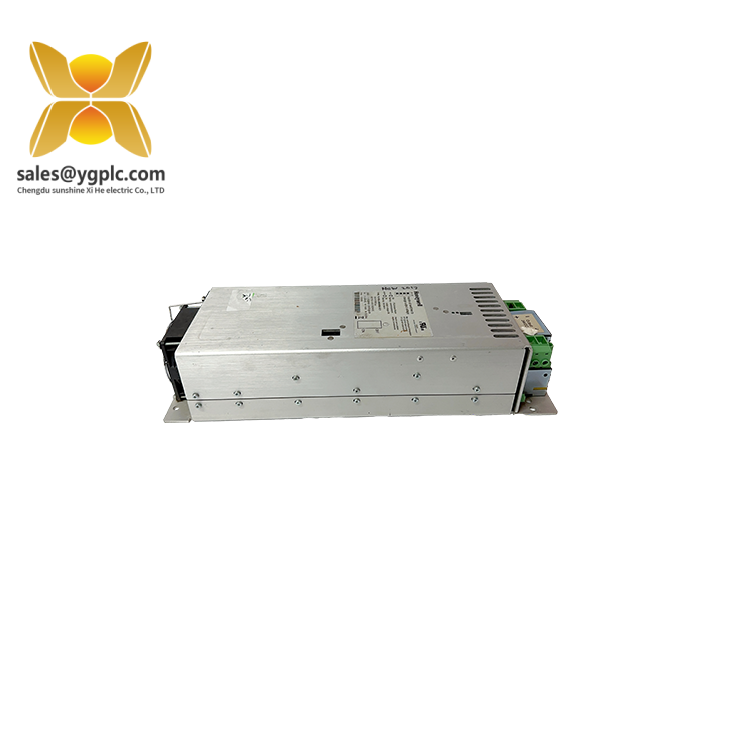
GE VLC-853-E
Application Scenarios & Pain Points
Typical Application Scenarios
- Packaging & Conveying Machinery – Small standalone conveyor skids, filling stations, and labeler sub-units. Local valve and photoeye logic runs on VLC-853-E to avoid long home-run wiring to main PLC racks.
- Water & Wastewater Treatment – Remote lift pump stations, chemical dosing skids scattered across plant sites. RS485 Genius bus links multiple VLC-853-E units back to a central SCADA host.
- Automotive Component Assembly – Modular fixture stations on assembly lines. Each fixture uses one VLC-853-E to handle clamping, sensor detection and part ejection logic independently.
- Food & Beverage Processing – Small mixing tanks and conveyor transfer sections. Compact DIN rail footprint fits tight stainless steel field enclosures without extra expansion racks.
- HVAC Industrial Plant Units – Secondary air handler and exhaust fan control panels. Local fault alarming and run sequence logic works offline during central system maintenance windows.
Real-World Field Case
SOP Quality Transparency Inspection Process
1. Warehouse Receiving Inspection
- Source Traceability: Cross-check original factory packing slip and import customs documentation for serial number matching
- Anti-Counterfeit Verification: Scan unit serial number against GE factory database, validate hologram security labels
- Visual Condition Audit: Inspect PCB surface for corrosion, connector pins for bending, casing for scratches or yellow aging
- Accessory Matching: Verify original terminal connectors, installation guide and factory QC certificate included in packaging
2. Live Bench Functional Testing
- Test Environment: Full GE VersaMax rack simulation station with IC695CPU315 main controller
- Step 1 Power Self-Test: Apply 24 VDC supply, record all status LED boot sequence and indicator behavior
- Step 2 Bus Communication Test: Establish Genius RS485 handshake between VLC-853-E and main CPU, confirm stable data polling
- Step 3 Full I/O Simulation Test: Inject dry contact signals to all 8 digital inputs, trigger each of the 8 digital outputs to confirm full range operation
- Step 4 24-Hour Continuous Load Run: Log module surface temperature fluctuations under sustained I/O switching cycles
- Deliverable: Complete signed test report with timestamped photos and communication log screenshots; test video available upon client request
3. Electrical Safety Parameter Testing
- 500 VDC insulation resistance test between power bus and signal circuits, pass threshold set above 10 MΩ
- Ground continuity testing for DIN rail mounting earthing terminals
- Dielectric withstand test applied to power input terminals per GE VersaMax component standards
4. Firmware & Configuration Backup Validation
- Read and record current installed firmware revision (V2.10 to V4.02) on unit serial test logs
- Photograph factory default DIP switch and bus address jumper positions for client reference
- Export and store default logic backup file generated via Proficy Machine Edition software
5. Final QC & Protective Packaging
- Second inspector double-check all test records and visual condition before release
- Seal module in anti-static shielding bag
- Wrap with shock-absorbing bubble film and place into reinforced export carton
- Affix printed QC Passed sticker with inspection completion date and technician ID
Technical Pitfall Avoidance Guide
1. Firmware Revision Mismatch Risk
Avoidance Steps: Record exact firmware version from the failed module before ordering replacement; specify required revision range when submitting purchase orders. Our team can reflash module firmware to match site system standards before shipment.
Field Example: A machine integrator replaced a failed VLC-853-E unit without matching firmware last year. The main CPU threw persistent bus fault alarms for two full shifts until technicians downgraded the sub-controller firmware to match the central rack runtime version.
2. DIP Switch & Bus Address Jumper Misconfiguration
Avoidance Steps: Capture clear photos of original unit’s DIP switches and jumper placement prior to removal. Copy all address settings onto the new VLC-853-E before power-up. Critical reminder: Only 120 Ω bus termination jumpers at the two physical endpoints of the RS485 trunk line.
Field Note: This error generates more after-hours service calls than any other setup mistake; document all hardware switch positions with photos every time you swap VersaMax modules.
3. Terminal Block Pin Assignment Inconsistencies
Avoidance Steps: Download official GE VersaMax hardware wiring diagrams to cross-reference pin definitions before rewiring field cables. Prepare short adapter jumpers if legacy terminal blocks cannot be fully replaced.
Warning: Never rely solely on past wiring experience when replacing GE distributed control modules; pin layout revisions occur across VersaMax sub-controller generations.
4. System Power Budget Undercalculation
Avoidance Steps: Calculate total current draw for all local controllers and I/O blocks, reserve minimum 20% spare power capacity for future expansions. Add supplementary 24 VDC power modules if load approaches supply maximum rating.
Reference Data: Single VLC-853-E draws approximately 0.18 A at 24 VDC; a bank of eight units plus attached field sensors requires a minimum 5 A power supply unit.
5. ESD Damage During Field Installation
Avoidance Steps: Wear certified anti-static wrist straps grounded to cabinet earth bar; complete all module swaps on conductive anti-static matting. Increase humidity inside control enclosures during winter dry operating seasons.
Field Real Case: A maintenance technician swapped a VLC-853-E without static protection last winter. The module emitted smoke within 10 seconds of power-up, requiring emergency overnight spare shipment and unplanned overtime labor costs.
Compatibility & Replacement Matrix
- VLC-853-E → VLC-853-E : Direct drop-in replacement (identical pinout, bus protocol, firmware hardware platform)
- VLC-853-E → IC200VLC001 : Partial compatibility (Requires full logic re-download, different terminal block connector, jumper address layout changed)
- VLC-853-E → IC200MDL series discrete I/O blocks : Not compatible (MDL units lack independent local logic execution, only passive expansion I/O)
- VLC-853-E → VLC-860-E : Conditional compatible (Supports same Genius bus, extra analog channel capacity; must rework cabinet mounting cutouts and adjust power load calculations)
- VLC-853-E → VersaMax Micro CPU IC200UDR005 : Not direct replacement (Micro CPU uses separate Modbus serial port, incompatible Genius bus communication stack)