中文版
中文版

 Phone:
  Email:
  WhatsApp:
 Description
- GE PQMII-T20 | Genuine OEM Power Quality Monitor for Industrial Substations
Product Core Brief
- Model: GE PQMII-T20
- Brand: GE (Multilin Division)
- Series: Multilin PQMII Power Quality Analyzer Series
- Core Function: Real-time grid power quality monitoring and energy metering
- Condition: New Original Surplus, Non-refurbished
- Type: Power Quality Meter / Energy Monitoring Module
- Key Specs: 0.2% energy accuracy | Supports Modbus TCP/RTU | Harmonic analysis up to 63rd order
Key Technical Specifications
| Parameter | Value |
|---|---|
| Full Model Number | PQMII-T20 |
| Manufacturer Division | GE Multilin |
| Measurement Accuracy | 0.2% for energy, 0.5% for voltage/current |
| Harmonic Measurement Range | 2nd to 63rd order harmonics |
| Standard Communication Protocols | Modbus RTU, Modbus TCP, DNP3 |
| Rated Input Voltage | 120 V– 480 V AC (3-phase) |
| Auxiliary Power Supply | 85 V – 264 V AC / 90 V – 300 V DC |
| Sampling Rate | 256 samples per AC cycle |
| Mounting Standard | Panel mount, 1/4 DIN cutout |
| Operating Temperature Range | -20 °C to +60 °C |
| Storage Temperature Range | -40 °C to +85 °C |
| MTBF Rating | > 60,000 operating hours |
| Data Logging Capacity | 128 MB internal event & waveform storage |
Product Introduction
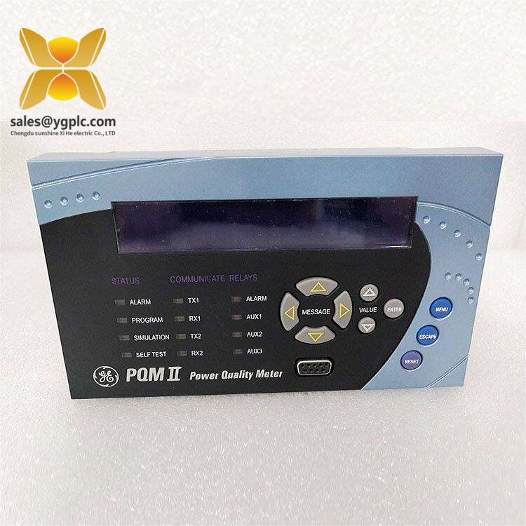
GE PQMII-T20
Application Scenarios & Pain Points
Typical Application Scenarios
- Industrial Manufacturing Plants – 3-phase workshop power monitoring
Track harmonics from variable frequency drives, welding machines and large motor loads; avoid equipment burnout caused by unbalanced current.
- Electrical Distribution Substations – Medium-low voltage feeder supervision
Record voltage sag/swell incidents, provide audit data for grid utility compliance inspections.
- Commercial Office Complexes – Building energy management
Measure total power consumption, identify high-loss circuits to cut utility operation costs.
- Data Center Facilities – Critical load power quality protection
Capture lightning transients and voltage deviations to protect servers and UPS systems.
- Renewable Energy Sites – Solar/Wind grid interconnection monitoring
Detect power factor drift and harmonic interference from inverter equipment.
Real Field Case
Compatibility & Replacement Matrix
- GE PQMII-T20 → GE PQMII-T10 : Partial compatibility (T10 lacks 63rd harmonic sampling; firmware v7.0+ required for matching communication mapping)
- GE PQMII-T20 → GE PQMII-T30 : Direct replacement (same cutout size, identical wiring terminals; T30 adds expanded data logging capacity)
- GE PQMII-T20 → GE EPM 7000 : Not compatible (different input voltage range, inconsistent Modbus register mapping, panel mounting dimensions mismatch)
- GE PQMII-T20 → Multilin PQMII-5000 : Need full wiring rework (CT/PT terminal pin definition differs; auxiliary power terminal layout changed)
SOP Quality Transparency Inspection Process
- Inbound Receiving Inspection
Trace original factory packing list and customs clearance documents; scan serial number against GE Multilin official database for genuine authentication. Full exterior inspection for casing scratches, corrosion or yellow aging; cross-check all original accessories: user manual, mounting brackets, terminal connectors and factory QC certificate.
- Live Bench Functional Test
Testing rack equipped with GE Multilin standard test power supply and Fluke 115 multimeter. Full power-on self-test to verify LED status indicators; complete Modbus TCP/RTU communication handshake with simulation PLC; simulate 3-phase unbalanced load for full-range voltage/current measurement test; continuous 26-hour aging run to record surface temperature change. Complete signed digital test report provided upon customer request, test photos or short video clips available for review.
- Electrical Safety Parameter Test
500 V megohmmeter insulation resistance test, standard pass threshold >10 MΩ; ground continuity check; dielectric withstand voltage test for input terminals.
- Firmware & Configuration Backup
Read and record factory firmware version; photograph DIP switch and communication jumper positions for reference; back up default register mapping data to offline storage.
- Final QC & Protective Packaging
Second inspector sign-off confirmation; sealed in anti-static shielding bag; wrapped with shock-absorbing bubble film then packed into thick export carton; attach printed QC Pass label with inspection date.
Technical Pitfall Avoidance Guide
1. Firmware Version Mismatch Risk
Avoidance Steps: Record firmware version of existing meter before ordering; clearly specify required firmware revision range to suppliers; firmware flash upgrade or downgrade service available if version conflict exists.
Field Case: A power station engineer replaced an old PQMII-T20 with new stock unit carrying v8.2 firmware. Their SCADA only supported v6.5 register tables, leading to three hours of offline system adjustment until firmware rollback was completed.
2. CT Polarity & Wiring Terminal Misalignment
Avoidance Steps: Take clear photos of all CT/PT wiring before removing old meter; strictly follow GE Multilin wiring schematic; test power flow direction immediately after power-up.
Warning Note: Even small wiring polarity mistakes will make all energy billing data unusable for utility audit.
3. Improper ESD Handling
Avoidance Steps: Wear certified anti-static wrist strap during disassembly and installation; place meter on anti-static mat before wiring; avoid direct contact with circuit board terminals.
Field Lesson: A subcontractor installed a PQMII-T20 without ESD protection in winter; unit failed after 10 minutes of energization with no visible damage, requiring full replacement at extra procurement cost.
4. Auxiliary Power Supply Capacity Shortage
Avoidance Steps: Calculate total power draw of all panel-mounted instruments, reserve minimum 20% extra power capacity; separate power quality meters from low-power PLC I/O modules on different supply circuits.
Reference Data: Single GE PQMII-T20 consumes around 12 VA at full sampling load; stacking 5 units requires a minimum 100 VA auxiliary power source.
5. Ignoring Bus Termination Resistor Setting
Avoidance Steps: Only activate built-in 120 Ω termination resistor on the first and last meter of the RS485 bus segment; disable resistor jumpers on all intermediate devices.