中文版
中文版

 Phone:
  Email:
  WhatsApp:
 Description
- GE Multilin 239 | Multilin 239 Motor Management Relay, Factory Bench Tested
Product Core Brief
- Model: Multilin 239
- Brand: GE Vernova (GE Digital Energy Multilin Series)
- Series: Multilin 200 Series Motor Protection & Management Relays
- Core Function: All-in-one digital relay for 3-phase AC motor fault protection, metering and SCADA communication
- Condition: New Original Surplus, No repair solder or component replacement traces
- Type: Motor Protection & Management Relay
- Key Specs: 70–265 VAC / 90–300 VDC auxiliary power | RS485 Modbus RTU | Optional 3-channel RTD input
- Note: ⚠️ Legacy production line discontinued, limited available stock
Key Technical Specifications
| Parameter Item | Technical Value |
|---|---|
| Full Model Designation | Multilin 239 (suffix variants: 239-RTD, 239-AN, 239-RTD-AN) |
| Auxiliary Operating Power | 70–265 VAC 50/60 Hz, 90–300 VDC; 20 VA power draw |
| CT Secondary Input Support | 1 A or 5 A phase CT, 1 A/5 A ground fault CT |
| Built-in Protection Elements | Thermal overload (15 selectable curves), locked rotor jam, single phasing, current unbalance, short circuit, ground fault, undercurrent, overtemperature, start supervision |
| Temperature Monitoring | Optional 3-channel RTD (Pt100/Ni120/Cu10) or stator thermistor input |
| Communication Interface | 2-wire RS485, Modbus RTU; baud rate 1200–19200 bps |
| Analog Output (Option) | 0–1 mA or 4–20 mA proportional thermal capacity meter |
| Output Contact Ratings | Trip/Alarm/Aux/Service relays: 10 A resistive @ 250 VAC |
| Fault Data Logging | Stores last 5 trip records with phase current, ground current and RTD values |
| Operating Ambient Temp | -20 °C to +70 °C panel-mounted |
| Storage Temperature | -40 °C to +85 °C |
| Insulation Resistance | ≥10 MΩ at 500 VDC dielectric test |
| MTBF Rating | >56,000 operating hours under nominal load |
| Mounting Standard | Standard 1/4 DIN panel cutout mounting |
| Configuration Software | EnerVista 239 Setup, Windows-compatible, field-upgradable firmware |
Product Introduction
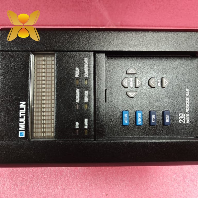
Multilin 239
Application Scenarios & Pain Points
Typical Application Scenarios
- Water & Wastewater Treatment Plants – Pump motor control panels. Ground fault and thermal RTD monitoring prevents submerged pump winding damage from seal leakage.
- Oil & Gas Refineries – Process compressor and cooling fan MCC feeders. Fast short-circuit and jam protection avoids process shutdown from seized rotating equipment.
- Mining & Aggregate Facilities – Conveyor belt and crusher motor starters. Start supervision feature blocks repeated rapid motor restarts that overheat rotors.
- HVAC Industrial Plants – Large air handler and exhaust fan control. Undercurrent alarm detects broken fan belts or coupling failure before motor stall.
- Food & Beverage Processing – Mixer and packaging machine motors. Multiple setting groups support multi-speed motor operating modes without hardware swap.
Real-World Field Case
SOP Quality Transparency Inspection Process
1. Warehouse Receiving Inspection
- Source Traceability: Cross-check factory packing slip, serial number matching unit front panel label and import customs documentation
- Anti-Counterfeit Verification: Validate GE Multilin printed branding, factory part suffix marking and hologram security sticker
- Visual Condition Audit: Inspect front LCD screen for dead pixels, terminal screw terminals for corrosion, PCB rear side for rework solder marks or component replacement
- Accessory Matching: Verify original USB configuration cable, mounting gaskets and factory test certificate included with unit
2. Live Bench Functional Testing
- Test Environment: GE secondary current injection test set, programmable 240 VAC auxiliary power supply, EnerVista 239 PC software workstation
- Step 1 Power & Display Boot Test: Apply rated control power, confirm full LCD startup sequence and all status LED indicators operate correctly
- Step 2 Modbus Communication Test: Establish stable RS485 Modbus RTU polling between relay and PC software, verify read/write access to all setting groups
- Step 3 Full Protection Element Injection Test: Inject phase overload, locked rotor, single-phase unbalance and ground fault signals to validate accurate trip timing and contact actuation
- Step 4 24-Hour Continuous Aging Run: Maintain nominal simulated motor load, log LCD metering stability and internal PCB temperature fluctuation
- Deliverable: Signed full test report with injection test waveform screenshots; bench test operation video available upon client request
3. Electrical Safety Parameter Testing
- 500 VDC insulation resistance test across CT secondary, control power and communication circuits, pass threshold ≥10 MΩ
- Continuity test for protective earth ground terminal
- Dielectric withstand hipot test for all isolated input/output circuits per ANSI relay safety standards
4. Firmware & Configuration Backup Validation
- Read and record installed firmware revision stored in relay flash memory
- Photograph factory default DIP switch and RS485 address jumper positions for on-site commissioning
- Export blank standard motor setting template file compatible with EnerVista software for customer commissioning reference
5. Final QC & Protective Packaging
- Second inspector cross-verify all test logs, LCD screen and terminal physical condition
- Place relay into anti-static shielding bag and heat-seal
- Wrap with shock-absorbing bubble foam and pack into reinforced export carton
- Affix printed QC Passed sticker with inspection completion date and technician ID
Technical Pitfall Avoidance Guide
1. Mismatched Relay Suffix Variant Missing RTD/Analog Hardware
Avoidance Steps: Record full suffix code (239 / 239-RTD / 239-AN / 239-RTD-AN) printed on the failed unit nameplate before placing spare orders. Specify required options clearly in procurement requests.
Field Example: A chemical plant ordered standard Multilin 239 without RTD inputs last spring; technicians discovered the missing temperature channels after panel wiring completion, delaying pump startup by 3 working days.
2. CT Secondary Open-Circuit Wiring Risk During Replacement
Avoidance Steps: Use GE 515 test blocking module to short all CT circuits before removing the relay from panel cutout; only open CT shorts after new relay CT terminals are fully wired and tightenedGE Vernova.
Critical Warning: Never energize CT circuits with open secondary wiring.
3. Firmware Version Mismatch with EnerVista Software
Avoidance Steps: Match EnerVista software release version to relay firmware; our bench team can upgrade or downgrade unit firmware to align with site existing software versions before shipment.
4. Incorrect RS485 Bus Termination Jumper Setup
Avoidance Steps: Set termination jumper ON only for the first and last Multilin 239 units on the RS485 bus segment; disable termination for all intermediate relays.
5. ESD Damage During Panel Replacement
Avoidance Steps: Wear grounded anti-static wrist strap connected to cabinet earth bar; place spare relay on conductive anti-static mat before mounting. Increase panel enclosure humidity during winter dry operating seasons.
Field Real Case: A maintenance technician swapped a Multilin 239 without static protection last winter. The Modbus RS485 port failed instantly after power application, requiring emergency air freight spare delivery and unplanned overtime labor.
Compatibility & Replacement Matrix
- Multilin 239 (base) → Multilin 239 : Direct drop-in replacement (identical panel cutout, terminal pinout, firmware platform, Modbus stack)
- Multilin 239 → Multilin 239-RTD / 239-AN / 239-RTD-AN : Partial compatibility (Same mechanical form factor; wiring must add RTD/analog signal terminals if temperature/4–20mA output functions are required)
- Multilin 239 → Multilin 339 : Conditional compatible (Expanded protection logic; larger panel cutout, different terminal layout, full setting rework mandatory)
- Multilin 239 → Multilin 469 / 489 Motor Relays : Not compatible (Larger footprint, different CT input wiring, incompatible Modbus register mapping)
- Multilin 239 → Electromechanical Bi-Metal Overload Relays : Not direct replacement (No thermal modeling, no fault logging, no Modbus communication, cannot detect unbalance or ground faults)