中文版
中文版

 Phone:
  Email:
  WhatsApp:
 Description
- GE MMII-PD-1-2-120 | 120V Input Power Drive Module for CNC & Automation Equipment
Product Core Brief
- Model: MMII-PD-1-2-120
- Brand: GE Fanuc Automation (Multi-Mod II Motion Control Series)
- Series: MMII (Multi-Mod II) Servo Drive Sub-Module Platform
- Core Function: Power stage amplifier to drive single-axis servo motors under MMII rack controller logic
- Condition: New Original Surplus, No refurbishment or repair solder traces
- Type: Servo Power Drive Module
- Key Specs: 120 VAC control input, single axis output, rack backplane communication
- Note: ⚠️ Original manufacturing discontinued, limited stock available
Key Technical Specifications
| Parameter Item | Technical Value |
|---|---|
| Full Part Number | MMII-PD-1-2-120 |
| Control Supply Voltage | 120 VAC 50/60 Hz |
| Axis Capacity | Single servo motor axis per module |
| Backplane Bus | Proprietary MMII Multi-Mod rack communication bus |
| Built-in Protection | Overcurrent, overvoltage, overtemperature, short-circuit shutdown |
| Cooling Method | Convection cooling with integrated aluminum heat sink |
| Operating Ambient Temp | 0 °C to +55 °C inside sealed control cabinet |
| Storage Temperature | -40 °C to +85 °C |
| Insulation Resistance | ≥10 MΩ at 500 VDC isolation test |
| MTBF Rating | >49,000 operating hours under nominal rated load |
| Form Factor | Standard MMII rack plug-in slide module |
| Mounting | Dedicated Multi-Mod II rack card slot mounting |
| Status Indicators | Power OK, Fault, Drive Enable LED front panel indicators |
Product Introduction
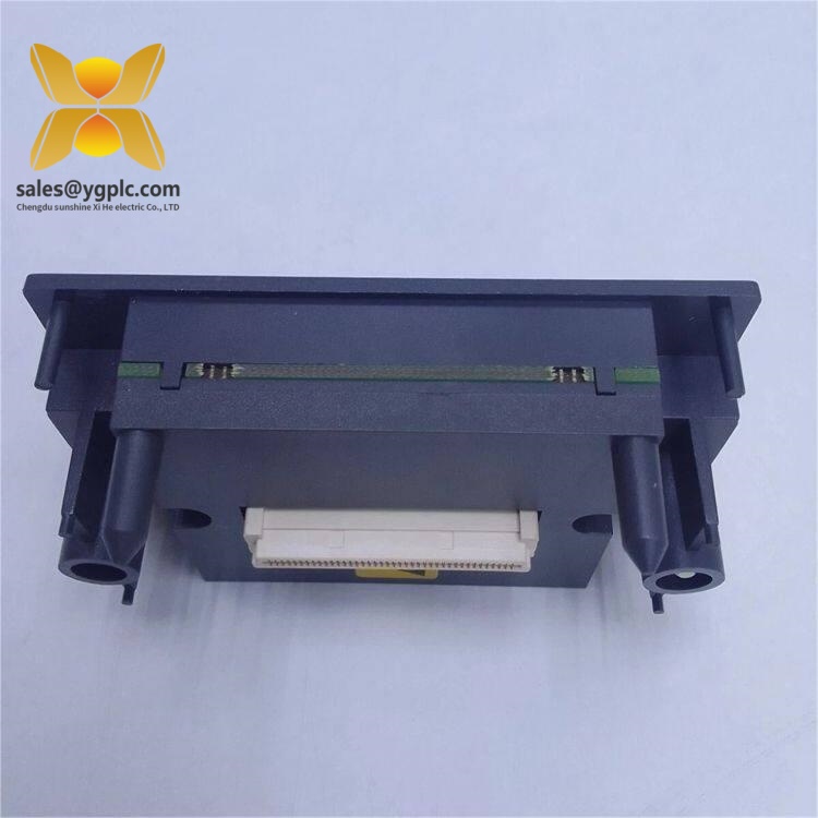
GE MMII-PD-1-2-120
Application Scenarios & Pain Points
Typical Application Scenarios
- CNC Machining Centers – Multi-axis milling and lathe equipment with GE Fanuc MMII motion control racks. Delivers precise spindle and linear axis servo power output.
- Automated Assembly Lines – Robotic pick-and-place stations, conveyor positioning tables, indexing fixture servo axes.
- Metal Stamping & Press Equipment – Servo feed control for sheet metal blanking, accurate stroke positioning with fast fault protection.
- Packaging Machinery – Filling, labeling and carton sealing multi-axis servo positioning systems.
- Aerospace Component Test Equipment – Precision motion simulation benches requiring stable closed-loop servo power amplification.
Real-World Field Case
SOP Quality Transparency Inspection Process
1. Warehouse Receiving Inspection
- Source Traceability: Cross-check factory packing slip, serial number printed on heat sink and original GE part marking
- Anti-Counterfeit Verification: Confirm GE Fanuc MMII series branding, molded front panel label and factory revision stamp
- Visual Condition Audit: Inspect power terminal lugs for corrosion, edge backplane connector pins for bending, heat sink for deformation, no aftermarket rework solder marks
- Accessory Matching: Verify original rack mounting slide rails and factory QC test certificate included
2. Live Bench Functional Testing
- Test Environment: Complete GE MMII rack test chassis, 120 VAC programmable power supply, dummy servo motor load simulator
- Step 1 Power Boot Self-Test: Apply rated 120 VAC control supply, record front panel LED power/fault boot sequence, confirm no persistent fault lights
- Step 2 MMII Backplane Communication Test: Establish stable command data exchange between PD module and MMII main CPU board
- Step 3 Full Axis Load Simulation Test: Simulate continuous servo acceleration/deceleration cycles, verify overcurrent and short-circuit protection triggers as designed
- Step 4 24-Hour Continuous Aging Run: Maintain medium servo load cycling, log heat sink temperature fluctuation and drive signal stability
- Deliverable: Signed full test report with fault trigger log screenshots; bench test operation video available upon client request
3. Electrical Safety Parameter Testing
- 500 VDC insulation resistance test between control power circuit and servo motor output circuits, pass threshold ≥10 MΩ
- Ground continuity test for rack mounting earthing terminals
- Dielectric withstand hipot test for all power isolation circuits per industrial motion drive safety standards
4. Firmware & Configuration Backup Validation
- Read and record embedded drive control firmware revision onboard the power module
- Photograph factory default backplane address jumper positions for on-site rack commissioning
- Save standard axis parameter preset file compatible with GE MMII motion programming software
5. Final QC & Protective Packaging
- Second inspector cross-verify all test logs and physical module condition
- Seal drive module inside anti-static shielding bag
- Wrap with shock-absorbing bubble foam and pack into reinforced export carton
- Affix printed QC Passed sticker with inspection completion date and technician ID number
Technical Pitfall Avoidance Guide
1. Control Voltage Variant Mismatch
Avoidance Steps: Record full model suffix “-120” from the failed module’s nameplate before ordering spares; strictly match control voltage rating to site cabinet power distribution.
Field Example: A metal fabrication shop substituted a 240V MMII-PD module for their faulty 120V unit last year. The servo axis failed to hold position, halting machining production for 2 full shifts until the correct 120V spare arrived.
2. Backplane Address Jumper Duplication
Avoidance Steps: Take clear photos of jumper positions on the defective module before removal; copy address settings exactly to the replacement unit, ensure unique address per axis slot in the MMII rack.
3. Servo Motor Wiring Short Circuits During Replacement
Avoidance Steps: Perform continuity and insulation resistance testing on servo motor cables before connecting to the new drive module; isolate shorted wiring before rack power restoration.
4. Insufficient Cabinet Ventilation
Avoidance Steps: Maintain continuous cabinet cooling fan operation; leave one empty slot between high-power PD modules for heat dissipation clearance.
Reference Data: Continuous full rated servo load is only guaranteed at ambient ≤45 °C; cabinet temperature above 55 °C activates thermal protection and limits motor torque output.
5. ESD Damage During Rack Module Swap
Avoidance Steps: Wear grounded anti-static wrist strap connected to the MMII rack earth bar; place spare drive module on conductive anti-static mat before sliding into rack slots. Increase cabinet humidity during dry winter maintenance windows.
Field Real Case: A machine technician replaced an MMII-PD-1-2-120 without static protection last winter. One servo output channel failed instantly, requiring emergency air shipment of replacement hardware and unplanned overtime labor costs.
Compatibility & Replacement Matrix
- MMII-PD-1-2-120 → MMII-PD-1-2-120 : Direct drop-in replacement (identical 120V power rating, rack pinout, backplane communication, drive firmware platform)
- MMII-PD-1-2-120 → MMII-PD-1-2-240 : Partial compatibility (Same mechanical rack form factor; incompatible control voltage, cabinet power wiring rework mandatory)
- MMII-PD-1-2-120 → MMII-PD-2 series dual-axis power modules : Conditional compatible (Shared MMII rack bus; dual-axis hardware cannot be configured as single-axis drop-in without program modification)
- MMII-PD-1-2-120 → Standalone GE Fanuc servo amplifiers : Not compatible (No MMII backplane communication interface, full motion program rewrite required)
- MMII-PD-1-2-120 → Third-party generic servo drives : Not compatible (Incompatible proprietary MMII rack command bus, cannot interface with existing MMII CPU logic)