中文版
中文版

 Phone:
  Email:
  WhatsApp:
 Description
- GE IS215AEPAH1CA | Genuine GE Vernova Alternative Energy Power Assembly Card
Product Core Brief
- Model: GE IS215AEPAH1CA
- Brand: GE Vernova (Former GE Energy / GE Fanuc)
- Series: Mark VIe Wind Turbine Control System
- Core Function: Real-time pitch axis drive signal processing & power control for wind turbine blades
- Condition: New Original Surplus, Non-refurbished, factory conformal coated
- Type: AEPA (Alternative Energy Power Assembly) Pitch Control Board
- Key Specs: IONet 100Mbps Ethernet | Compatible with BPPC Processor | Supports ControlST V4.06+

Key Technical Specifications
| Parameter | Value |
|---|---|
| Full Part Number | IS215AEPAH1CA |
| Functional Name | Wind Pitch Axis AEPA Control Assembly |
| Backplane Interface | Mark VIe standard VME rack slot |
| Main Communication | Dual IONet 100 Mbps Ethernet ports |
| Supported CPU Board | IS210BPPCH1AC BPPC Wind Processor |
| Mandatory Software Version | ControlST V04.06 or newer |
| Input Backplane Power | 24 V DC nominal |
| Onboard Output Drive Capacity | 10 A peak for pitch servo drive loops |
| PCB Protection | Full conformal coating against dust & humidity |
| Operating Temperature | -40 °C to +85 °C |
| Shock / Vibration Rating | 30 g 11ms shock, 5 g RMS 10–500 Hz vibration |
| Humidity Tolerance | 0–95% RH non-condensing |
| MTBF Rating | > 68,000 operating hours under wind farm conditions |
| Onboard Diagnostics | Continuous self-test for short circuit, overheat & communication loss |
| Enviroment Compliance | IEC 60068 industrial harsh environment standards |
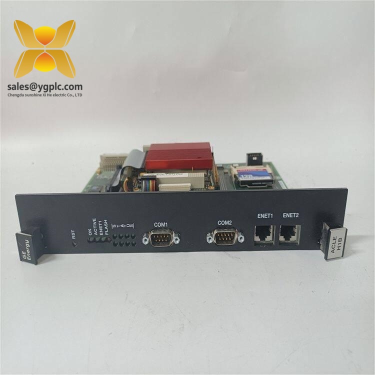
GE IS215AEPAH1CA
Product Introduction
Application Scenarios & Pain Points
Typical Application Scenarios
- Onshore Utility Wind Farms – Multi-MW variable pitch turbine control
Stable blade angle regulation under gusty wind conditions; real-time fault reporting to wind farm central monitoring platform.
- Offshore Wind Power Platforms – Salt fog harsh environment operation
Conformal coated PCB resists salt air corrosion, reducing annual board replacement frequency.
- Mountain High-Altitude Wind Parks – Wide temperature fluctuation operation
-40°C cold-start compatible design avoids pitch drive lockout during winter low-temperature nights.
- Distributed Industrial Wind Generators – Factory self-consumption turbines
Compact VME rack form factor fits small on-site control cabinets without extra expansion racks.
- Wind Farm Retrofit Upgrade Projects – Legacy Mark VIe wind rack modernization
Direct drop-in replacement for outdated IS215AEPAH1A without full rack rewiring.
Real Field Case
Compatibility & Replacement Matrix
- GE IS215AEPAH1CA → GE IS215AEPAH1A : Partial compatibility (same rack pinout; H1A lacks salt-fog conformal coating; ControlST firmware V4.06 upgrade mandatory)
- GE IS215AEPAH1CA → GE IS215AEPAH1C : Direct hardware replacement (identical mechanical size, IONet port layout; minor firmware register mapping adjustment needed post-install)
- GE IS215AEPAH1CA → GE IS215WEMAH1BB : Not compatible (WEMAH board for generator converter control, no pitch drive output circuits)
- GE IS215AEPAH1CA → GE IS215MACCH3A : No cross-compatibility (MACCH board for general analog conversion, missing pitch servo power amplification stage)
SOP Quality Transparency Inspection Process
- Inbound Receiving Inspection
Trace original GE factory packing list and customs clearance documents; scan serial number against GE Vernova official component database for OEM authenticity validation. Full PCB visual inspection for coating scratches, component solder joint cracks or transport deformation; cross-check matching accessories: rack ejector latches, terminal jumpers, original datasheet and factory test certificate.
- Live Bench Functional Test
Test bench equipped with Mark VIe BPPC simulation rack and Fluke 115 industrial multimeter. Full 24VDC backplane power-on self-test to verify LED status indicators and IONet link handshake; simulate full-range pitch angle setpoint signals to validate servo power output linearity; continuous 26-hour thermal aging run to track PCB temperature stability under full load. Signed digital test report, live communication test screenshots and inspection photos can be delivered to customers upon request.
- Electrical Safety Parameter Test
500 V megohmmeter insulation resistance test with pass threshold >10 MΩ between signal circuits and rack ground; full ground continuity verification; dielectric withstand voltage test for all pitch drive output terminals.
- Firmware & Configuration Backup
Read and record factory preloaded board logic version; photograph IONet address jumpers and pitch current limit DIP switch positions; back up default fault threshold parameters for post-replacement commissioning reference.
- Final QC & Protective Packaging
Second dedicated inspector full sign-off confirmation; sealed in anti-static shielding bag; wrapped with shock-absorbing bubble film then packed into reinforced export carton; attach printed QC Pass inspection label with unique serial number and full test date.
Technical Pitfall Avoidance Guide
1. ControlST Firmware Version Mismatch Risk
Avoidance Steps: Record existing software revision before ordering replacement boards; specify minimum V4.06 firmware to suppliers; complete rack software upgrade before board swap if site runs outdated ControlST releases.
Field Case: A wind farm technician swapped H1A boards with CA variants without updating control software. The turbine lost pitch control for 3 hours during night operation until on-site engineers upgraded the BPPC processor firmware.
2. IONet Bus Termination Resistor Misconfiguration
Avoidance Steps: Only activate internal termination jumpers on the first and last rack cards of each IONet segment; disable resistors on all intermediate IS215AEPAH1CA units.
Warning Note: Intermittent IONet faults only appear under high wind load, making them difficult to replicate during ground bench testing.
3. Improper ESD Handling During Rack Installation
Avoidance Steps: Wear certified anti-static wrist strap before extracting/inserting rack cards; place the AEPA board on an anti-static mat before connecting pitch drive wiring; avoid direct finger contact with PCB traces and Ethernet port pins.
Field Lesson: A subcontractor replaced an AEPA board at a northern wind site in January without ESD protection; the unit generated erratic blade angle signals after energization, requiring emergency air shipment of a spare module.
4. Pitch Servo Overload Parameter Mismatch
Avoidance Steps: Photograph current-limit DIP switch positions from the original faulty board before removal; replicate all switch settings on the replacement CA board before rack insertion.
Reference Data: Standard 2.5 MW turbine pitch motors require 7–9 A peak current threshold; misconfigured limits will lock blade angle during wind gust response.
5. Salt Fog Corrosion from Damaged Conformal Coating
Avoidance Steps: Inspect full PCB coating surface before acceptance; handle boards only by metal rack latches, never grip the PCB circuit area; store spare AEPA boards in humidity-controlled anti-static cabinets off-tower.