中文版
中文版



 Phone:
  Email:
  WhatsApp:
 Description
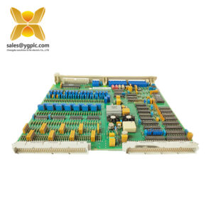
- GE IS200EGPAG1BEC | Genuine GE Vernova EX2100 Power Bridge Control Board
Product Core Brief
- Model: IS200EGPAG1BEC
- Brand: GE Vernova (Former GE Industrial Systems / GE Speedtronic)
- Series: EX2100 / EX2100e Generator Excitation Control System
- Core Function: Amplify gate firing pulses to drive six SCRs on excitation power bridge, monitor thermal protection signals
- Condition: New Original Surplus, Non-refurbished, factory conformal coated & burn-in tested
- Type: EGPA Exciter Gate Pulse Amplifier PCB Board
- Key Specs: 6-channel SCR gate drive | 125VDC EPDM power input | 5 configurable jumpers | Dual thermal switch monitoring

Key Technical Specifications
| Parameter | Value |
|---|---|
| Full Part Number | IS200EGPAG1BEC (Rev B/E/C) |
| Official Functional Name | EGPA Exciter Gate Pulse Amplifier |
| Supported SCR Count | Up to 6 silicon controlled rectifiers for excitation bridge |
| Main Power Input | 125 V DC, supplied from EPDM Exciter Power Distribution Module |
| Onboard Power Conversion | Integrated DC/DC converter for isolated gate pulse output |
| Thermal Switch Trigger Threshold | Alarm at 170°F, Trip at 190°F (two independent Klixon thermal sensors) |
| Configuration Hardware | 5 configurable on-board jumpers for site application matching |
| Status Indicators | Multi-color LED array: gate power, firing pulse, bridge temp, fault/alarm, airflow |
| Signal Isolation | Opto-coupled gate command input from ESEL control board |
| PCB Protection | Full conformal coating for dust, humidity and mild salt fog resistance |
| Operating Temperature | -40 °C to +70 °C cabinet ambient |
| Humidity Rating | 0–95% RH non-condensing |
| MTBF Rating | > 414,000 operating hours under standard generator load conditions |
| Mechanical Dimension | 168 mm × 150 mm × 55 mm rack card form factor |
| Weight | Approx. 0.7 kg |
| Compatibility Platform | GE EX2100, EX2100e generator excitation control racks |
Product Introduction
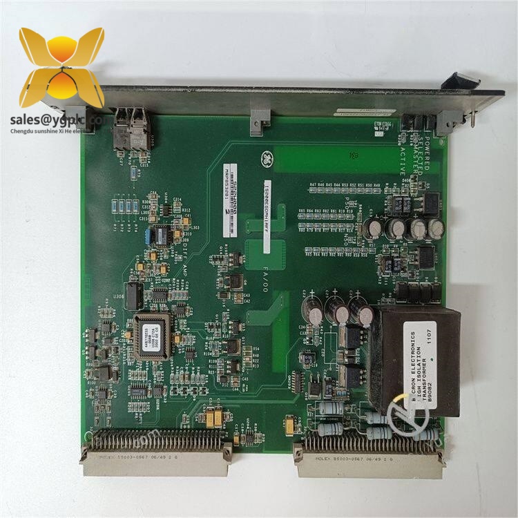
GE IS200EGPAG1BEC
Application Scenarios & Pain Points
Typical Application Scenarios
- Fossil Fuel Steam Turbine Generators – EX2100 Main Excitation Cabinets
Stable SCR firing control for large synchronous generators; graded thermal alarm prevents catastrophic rectifier burnout.
- Combined Cycle Gas Turbine Power Plants – HRSG Generator Excitation Racks
Wide temperature tolerance adapts to fluctuating auxiliary cabinet ambient heat from turbine exhaust.
- Hydropower Station Generator Units – Low-speed hydro generator excitation control
Configurable jumper settings match variable excitation demand for seasonal water flow load changes.
- Coastal Offshore Power Cogeneration Facilities – Salt fog harsh environment operation
Conformal coating mitigates PCB trace oxidation from marine humidity and salt particles.
- Power Plant Retrofit Upgrade Projects – Obsolete EX2100 EGPA card replacement
Drop-in rack slot fit with identical terminal pinout, no cabinet rewiring required.
Real Field Case
Compatibility & Replacement Matrix
- GE IS200EGPAG1BEC → GE IS200EGPAG1BE : Direct hardware replacement (identical terminal layout; minor jumper reconfiguration needed post-install)
- GE IS200EGPAG1BEC → GE IS200EGPAG1A : Partial compatibility (same rack slot footprint; Rev A lacks enhanced thermal fault logic, firmware adjustment mandatory)
- GE IS200EGPAG1BEC → GE IS200EPCTG1A : Not compatible (EPCT board for excitation current transducer signal conditioning, no SCR gate drive circuits)
- GE IS200EGPAG1BEC → Siemens T3000 Excitation Amplifier Card : Full cabinet rework required (different bus communication, mismatched SCR firing voltage, incompatible rack mechanical form factor)
SOP Quality Transparency Inspection Process
- Inbound Receiving Inspection
Trace original GE factory packing slip and customs clearance documents; scan serial number against GE Vernova EX2100 component database for OEM authenticity validation. Full PCB visual inspection for conformal coating scratches, capacitor bulging, relay contact oxidation or connector pin deformation; cross-check matching accessories: rack ejector latches, terminal jumper shunts, factory datasheet and original burn-in test certificate.
- Live Bench Functional Test
Test bench equipped with standard EX2100 rack backplane, EPDM 125VDC power supply and Fluke 115 industrial multimeter. Full power-on self-test to verify all LED status indicators and opto-coupled ESEL command handshake; simulate full-range SCR gate pulse output to validate six-channel drive linearity; inject thermal switch open-circuit signals to verify alarm/trip logic sequence; continuous 26-hour thermal aging run to track PCB temperature stability under full pulse load. Signed digital test report, pulse waveform screenshots and inspection photos can be provided to customers upon request.
- Electrical Safety Parameter Test
500 V megohmmeter insulation resistance test with pass threshold >10 MΩ between high-voltage gate drive circuits and rack ground; full ground continuity verification across PCB ground planes; dielectric withstand voltage test for all front-panel terminal connectors.
- Jumper & Configuration Backup
Photograph all five application configuration jumpers from the original faulty board before removal; record factory default jumper positions on the new IS200EGPAG1BEC unit for post-replacement commissioning reference.
- Final QC & Protective Packaging
Second dedicated inspector full sign-off confirmation; sealed in anti-static shielding bag; wrapped with shock-absorbing bubble film then packed into reinforced export carton; attach printed QC Pass inspection label with unique serial number and full test date.
Technical Pitfall Avoidance Guide
1. Jumper Configuration Mismatch Risk
Avoidance Steps: Take clear photos of jumper positions on the old EGPA board before dismounting; replicate every jumper shunt location exactly on the replacement IS200EGPAG1BEC unit before rack insertion; cross-reference EX2100 wiring manual to validate jumper logic for hydro/gas/steam generator types.
Field Case: A power station technician installed a new BEC board without copying original jumpers. The generator suffered excitation current imbalance for 4 hours until maintenance staff re-adjusted the five configuration jumpers per site drawing.
2. Thermal Switch Wiring Polarity Error
Avoidance Steps: Mark wire labels before disconnecting thermal switch cables; strictly follow terminal pin polarity defined in EX2100 service manual; manually short each thermal switch during commissioning to confirm LED alarm/trip light activation.
Warning Note: Polarity miswiring cannot be detected during bench power-up without physical thermal sensor simulation.
3. Improper ESD Handling During Rack Extraction
Avoidance Steps: Wear certified anti-static wrist strap before extracting/inserting EGPA rack cards; place the board on an anti-static mat before adjusting jumpers or connecting terminal wiring; avoid direct finger contact with PCB traces and front-panel connector pins.
Field Lesson: A subcontractor replaced an EGPA board in northern China winter without ESD protection; the unit generated erratic firing pulse outputs after energization, requiring emergency rush shipment of a spare IS200EGPAG1BEC.
4. Undersized EPDM 125VDC Power Supply Capacity
Avoidance Steps: Calculate total DC load of all rack EGPA cards, reserve minimum 20% extra power margin; separate excitation amplifier boards from low-voltage I/O modules on independent EPDM supply branches.
Reference Data: Single IS200EGPAG1BEC draws ~180mA steady-state 125VDC current; four EGPA boards require an EPDM module rated for minimum 1A continuous output.
5. Damaged Conformal Coating During Handling
Avoidance Steps: Handle boards only by metal rack ejector latches, never grip the PCB circuit surface; inspect full coating coverage upon receiving spare inventory; store unused EGPA boards in humidity-controlled anti-static storage cabinets off-rack.