中文版
中文版

 Phone:
  Email:
  WhatsApp:
 Description
- GE DS3800HIOC | Power Plant Gas & Steam Turbine Control Spare Part
Product Core Brief
- Model: DS3800HIOC
- Brand: GE General Electric
- Series: Speedtronic Mark IV DS3800 Turbine Control Series
- Core Function: High-level analog & discrete signal acquisition and output conditioning for turbine governing and safety interlock circuits
- Type: HIOC High Level Input/Output PCB Board
- Key Specs: Multi-channel conditioned signal ports | Backplane bus communication | Onboard signal filtering & surge suppression
- Condition: New Original Surplus, conformal coated PCB, no component replacement or disassembly
Key Technical Specifications
| Parameter Item | Detailed Value |
|---|---|
| Full Part Number | DS3800HIOC |
| Compatible System | GE Speedtronic Mark IV DS3800 Turbine Control Rack |
| Signal Processing Type | High-level pre-amplified analog + discrete trip/alarm signals |
| Onboard Hardware Filtering | RC low-pass noise filter for EMI suppression near generator cabinets |
| Backplane Interface | Standard Mark IV parallel rack bus, direct plug-in slot mounting |
| Front Panel Indicators | 3 status LEDs: Power, Active, Fault Diagnostic |
| Input Signal Range | 0–10 VDC analog, 24 VDC discrete digital inputs |
| Output Drive Capacity | Sink/source discrete logic signals for servo valve & relay actuation |
| PCB Protection | Conformal coating against dust, humidity and light chemical vapor |
| Operating Power | Derived from Mark IV rack backplane ±5 VDC / ±12 VDC bus |
| Typical Power Consumption | 2.6 W steady-state operation |
| Operating Ambient Temp | 0 °C to +60 °C indoor turbine cabinet |
| Storage Temperature | -40 °C to +85 °C |
| Humidity Tolerance | 5%–95% RH non-condensing |
| MTBF Rating | Over 50,000 hours under standard power station environment |
| Main Chipset Components | AD574 A/D converter, Xilinx logic array, X2816 EPROM firmware storage |
| Mechanical Form Factor | Standard Mark IV single-slot plug-in PCB layout |
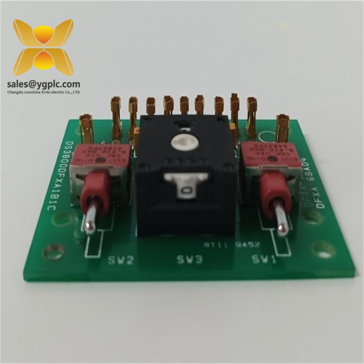
GE DS3800HIOC
Product Introduction
Application Scenarios & Pain Points
Typical Application Scenarios
- Combined-Cycle Power Plant Gas Turbine Mark IV Control Cabinets
Process high-level combustor pressure, exhaust thermocouple and compressor vibration signals; filter EMI from generator excitation cabinets to eliminate false trip logic.
- Thermal Power Station Steam Turbine Governing Racks
Transmit lube oil pressure, valve position feedback and bearing temperature analog signals to main CPU; route emergency discrete trip contact inputs for ETS protection chains.
- Refinery Cogeneration Turbine Automation Skids
Conformal coated PCB resists corrosive chemical vapor inside refinery control buildings; stable signal output drives fuel servo valve position control loops.
- Industrial Waste Heat Recovery Turbine Control Panels
Low power consumption and long MTBF reduce routine maintenance frequency for unattended industrial power units.
- Hydroelectric Plant Auxiliary Turbine Monitoring Systems
Multi-channel signal consolidation simplifies cabinet wiring for auxiliary governor and cooling system sensors.
On-site Application Case
A coastal cogeneration facility’s Mark IV gas turbine control rack generated continuous unstable pressure signal alarms traced to a faulty DS3800HIOC board. GE official supply chain could not deliver matching original boards for 56 days, overlapping fully with summer peak electricity generation window. Persistent signal drift risked unplanned full turbine shutdown with massive generation revenue loss.
Compatibility & Replacement Matrix
- DS3800HIOC → DS3800HIOC : Direct drop-in replacement; identical pinout, signal channel layout and rack dimensions, no potentiometer re-calibration required post-install
- DS3800HIOC → DS3820HIOC : Functional compatible replacement; updated PCB revision for newer Mark IV cabinet enclosures, minor analog offset potentiometer tuning recommended after swap
- DS3800HIOC → DS3800HIOB / DS3800HIDC : Partial compatibility; HIOB/HIDC handle low-level raw sensor signals without built-in high-level amplification, full channel scaling reconfiguration mandatory
- DS3800HIOC → Mark VI series I/O boards (IS200BPPBH2BMD) : System-level incompatible; different backplane bus architecture, cannot swap between Mark IV and Mark VI racks
SOP Quality Transparent Inspection Process
1. Warehouse Receiving Verification
- Source Traceability: Cross-check original GE factory packing slip, import customs records and unique PCB serial number matching
- Anti-counterfeit Validation: Inspect intact factory tamper seals and laser-etched board serial codes against GE spare part database
- Visual Appearance Test: Inspect PCB for scratches, conformal coating peeling, solder repair traces or bent backplane pins; verify three front-panel LEDs undamaged
- Accessory Matching: Match original rack mounting hardware, factory test certificate and Mark IV wiring reference manual
2. Live Bench Functional Test
- Test Environment: Complete Mark IV DS3800 simulation rack with DMPA main processor board, Fluke 115 multimeter and precision analog signal generator
- Test Content:
- Power-on self-test: Full circuit boot diagnostic, validate Power/Active/Fault LED operating status
- Multi-channel analog signal test: Inject standard 0–10 VDC reference signals to verify linear conversion accuracy
- Discrete input/output loop test: Simulate 24 VDC trip contact signals to confirm logic switching response
- Backplane bus communication handshake test: Transmit real-time signal data to Mark IV main CPU board
- Continuous 24-hour aging run: Monitor board surface temperature and signal drift magnitude
- Output: Signed formal test report with analog calibration logs, bench test screenshots and physical inspection photos; full test videos available upon customer request
3. Electrical Parameter Detection
- 500 V megger insulation resistance test for power and signal circuits, pass threshold >10 MΩ
- Surge suppression circuit performance verification against industrial transient voltage interference
- PCB trace continuity test to eliminate hidden open/short circuit defects
4. Firmware & Calibration Validation
- Record factory EPROM firmware version printed on PCB label
- Photograph onboard potentiometer adjustment positions and jumper layout for on-site installation reference
- Save default signal scaling parameter template files and provide digital copies with shipment
5. Final QC & Protective Packaging
- Dedicated QC inspector signs qualified inspection record, attach QC Passed sticker with inspection completion date
- Main PCB sealed inside anti-static shielding bag to prevent ESD damage during transit
- Wrap with shock-absorbing bubble film, place desiccant inside reinforced export carton to resist moisture during long-distance shipping
Component Replacement Risk Avoidance Guide
1. Unretained Potentiometer Calibration Values
Avoidance Measures: Capture clear close-up photos of all onboard trim potentiometers before powering down the faulty board; replicate identical adjustment positions on the replacement unit post hot-swap.
Real Site Case: A power plant maintenance engineer replaced the HIOC board without calibration photos; combustor pressure readings offset by 18%, consuming 8 hours of iterative potentiometer tuning to restore normal measurement accuracy.
2. ESD Damage During Unpacking & Rack Hot-Swap
Avoidance Measures: Wear certified anti-static wrist strap connected to cabinet grounding bar before opening anti-static packaging; place the board on an anti-static work mat during potentiometer adjustment.
Critical Reminder: Static breakdown is the top non-warranty failure mode for Mark IV signal conditioning boards; never touch PCB circuit traces with bare fingers.
3. Bent Backplane Connector Pins During Insertion
Avoidance Measures: Align both top and bottom rack slide rails evenly before pushing the board fully seated; lock front panel retention clips tightly and shake lightly to eliminate physical play.
4. Confusing HIOC with Low-Level HIOB/HIDC Boards
Avoidance Measures: Confirm full model number DS3800HIOC on the failed PCB label before purchasing spare parts; never order by partial short model numbers without cross-verification.
5. Ignoring Onboard EMI Filter Maintenance
Avoidance Measures: Inspect all surface-mount filter resistors and capacitors during pre-install visual check; avoid squeezing or bending PCB edges to prevent component detachment.