中文版
中文版

 Phone:
  Email:
  WhatsApp:
 Description
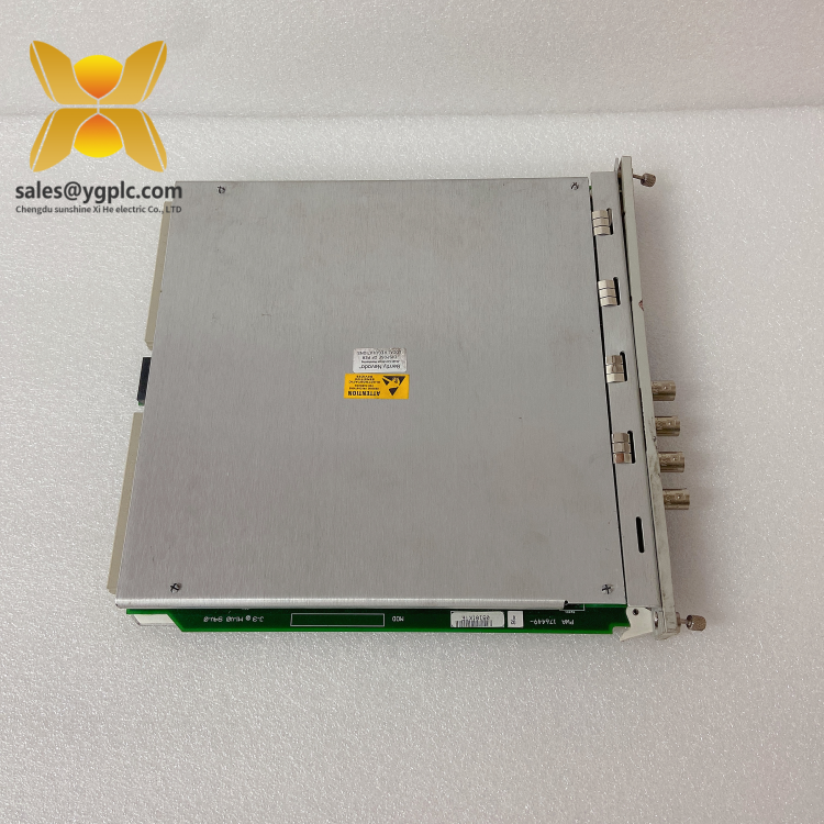
Bently Nevada 3500/33 16‑Channel Relay Module (149986‑01) – Alarm & Trip Outputs for API‑670 Machine Protection Racks
The Bently Nevada 3500/33 is a 16‑channel relay output module used to drive alarms, interlocks, and shutdown circuits from a 3500 protection rack. It’s typically chosen when you need flexible, highly reliable relay logic that follows machine‑protection events—Alert, Danger, Not‑OK—without extra external logic hardware. From my experience, it’s a straightforward way to tie your 3500 measurements into plant ESDs, PLCs, annunciators, and trip solenoids with clean, configurable behavior.

Key Features
- 16 configurable relay outputs – Each channel typically provides an isolated dry contact to drive alarms, trips, or interlocks.
- Alarm Drive Logic (ADL) – Flexible logic lets you combine multiple conditions (e.g., AND/OR of Alert, Danger, Not‑OK) to control each relay.
- Latching and voting options – Supports latching/non‑latching behavior, with 2‑out‑of‑3 voting when used in TMR rack configurations.
- Fail‑safe behavior – Relays can be set to energize or de‑energize on alarm; many sites prefer de‑energized on fault/power loss for safety.
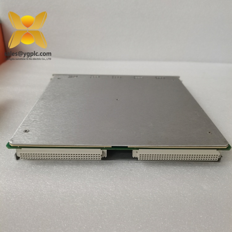
- Backplane integration – Communicates over the 3500 backplane; no external power needed and configuration is handled via the rack interface (TDI).
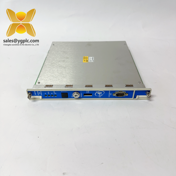
- Front module + rear I/O design – The rear I/O module handles field terminations, so swapping the front card rarely requires rewiring.
- System‑wide status visibility – Relay and channel status appear at the rack display and in software, which simplifies proof testing and audits.
Technical Specifications
| Brand / Model | Bently Nevada 3500/33 (P/N 149986‑01) |
| Function | 16‑channel relay output module for machine protection alarms and trips |
| Power Requirements | Powered via 3500 rack backplane; no external power to the module |
| Signal Input/Output | 16 isolated relay outputs (dry contacts); driven by 3500 monitor alarms and status |
| Communication Interfaces | Backplane interface to 3500/22M TDI for configuration and status reporting |
| Installation Method | Front relay module + matching rear I/O module; one full‑height rack slot |
| Dimensions & Weight | Standard 3500 series module form factor; consult rack datasheet for details |
| Operating Temperature | Per 3500 rack ratings; typically used in conditioned control cabinets |
| TMR/Voting Support | Supports 2‑out‑of‑3 voting when installed in TMR racks |
Application Fields
You might notice the 3500/33 in places where relay reliability really matters. Typical deployments include:
- Gas/steam turbines and large compressors – trip interlocks, fuel shutoff, and vibration‑based danger trips
- Pumps, fans, and expanders – annunciation of Alert/Danger states and permissives for startup sequences
- Generators and big motors – integration to DCS/PLC DI points for alarms, run inhibiting, and emergency stops
- Refining, petrochemical, and pipeline stations – tie‑ins to ESD/ESDVs and plant alarm panels for API‑670 compliance
Advantages & Value
- Reliability first – Proven 3500 architecture, with options to use fail‑safe and voting logic to reduce nuisance trips.
- Compatibility – Works natively with any 3500 monitor module; typically no external interposing relays for standard DI/annunciator loads.
- Lower wiring effort – Rear I/O terminations keep cabinet wiring tidy and make module replacement fast.
- Audit‑friendly – Clear status indication and logic documentation help during Functional Safety or API‑670 proof tests.
- Lifecycle support – Spares and field know‑how are widely available, which seems to keep ownership costs predictable.
Quick customer note from a turnaround last spring: “We mapped four danger conditions into a single 2oo3‑voted trip on the 3500/33. Proof testing went smoother than expected, and we cut false trips to near zero.”
Installation & Maintenance
- Cabinet environment – Mount in a 3500 rack within a clean, ventilated control cabinet. Keep ambient within the rack’s rating and allow front/rear service access.
- Wiring practices – Use appropriately rated field wiring to the relay contacts. For inductive loads (solenoids, relays), add snubbers or flyback diodes to protect contacts and reduce EMI.
- Grounding & segregation – Separate relay wiring from low‑level sensor cables where possible; bond shields at a single point to avoid loops.
- Commissioning – Verify Alarm Drive Logic, latching behavior, and fail‑safe settings. Perform a proof test of each relay to confirm contact operation and DCS/PLC indication.
- Routine care – Periodically actuate relays during planned outages, check terminal tightness, and review event logs for nuisance alarms. Firmware alignment with the rack/TDI is recommended.
- Spare strategy – Keeping a spare front 3500/33 and its matching rear I/O (e.g., 149986‑01 variant) typically shortens MTTR.
Quality & Certifications
- CE and UL/cUL compliance for 3500 series modules (region dependent)
- RoHS conformity for electronic assemblies in most markets
- Manufactured under ISO 9001 quality systems
- Typical manufacturer warranty: 1 year; extended coverage available in many cases
If you’re matching an existing rack, share the full module options and I/O part number so we can confirm exact compatibility—relay type and terminal style can vary slightly by 149986‑xx variant.