中文版


 Phone:
 Email:
 WhatsApp:
Description
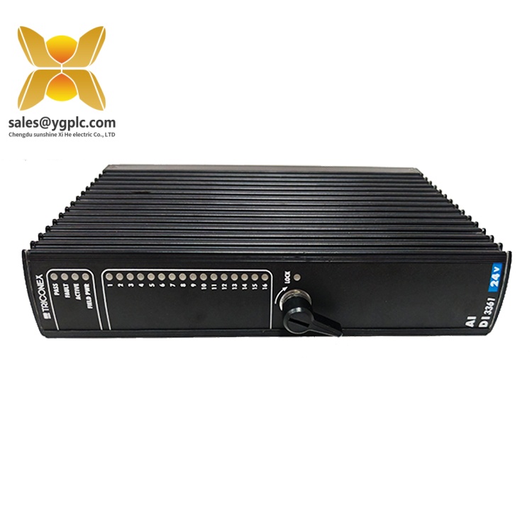
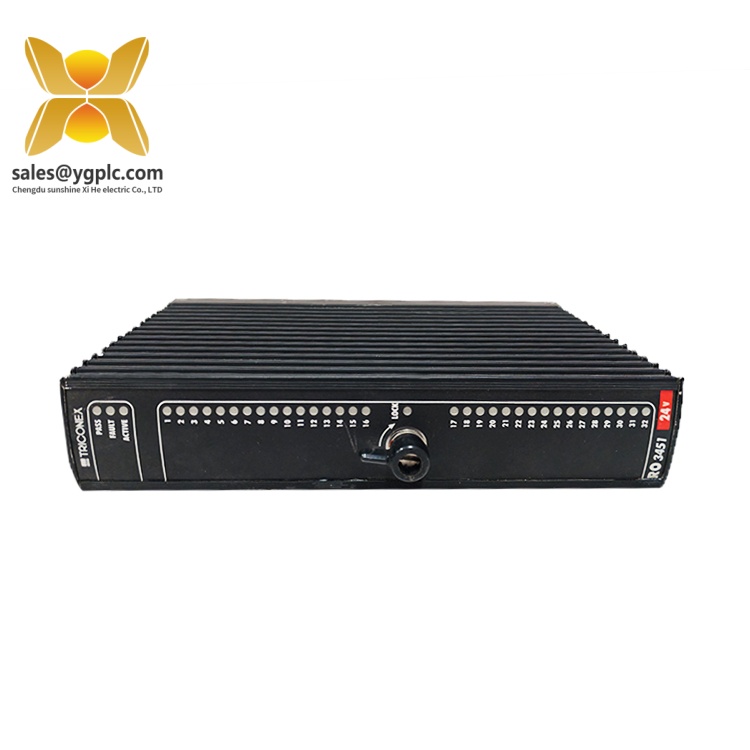
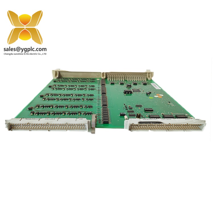
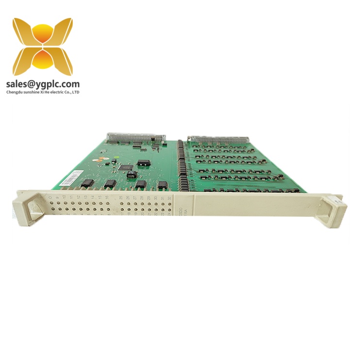
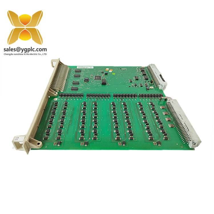
The ABB DSIH72VP ENOK is identified in industrial product listings as a digital input interface module. Descriptions associated with the DSIH72VP designation specify 16 digital inputs for 24 V DC signals, arranged in two electrically isolated groups of eight channels. Each input incorporates signal-conditioning and optical-isolation elements, while input status indicators support basic signal-state checks.
The DSIH72VP ENOK designation should be matched carefully against the installed unit before procurement or replacement. The available technical descriptions do not establish that every specification associated with DSIH72VP applies unchanged to the ENOK variant. System compatibility, terminal arrangements, electrical ratings, and configuration requirements should therefore be assessed using the exact hardware identification and the relevant control-system documentation.
Key Technical Specifications
| Parameter | Specification |
|---|---|
| Manufacturer | ABB |
| Model designation | DSIH72VP ENOK |
| Product type | Digital input interface module |
| Number of digital inputs | 16 |
| Nominal input voltage | 24 V DC |
| Input voltage range | 18–30 V DC |
| Input current | 6 mA at 24 V |
| Input arrangement | Two isolated groups of eight channels |
| Input isolation | Optical isolation |
| Input status indication | Individual input status LEDs |
| Voltage monitoring | Process-voltage supervision inputs |
Detailed Product Overview
Product Function
The ABB DSIH72VP ENOK is an industrial control-system component identified by its model designation. The DSIH72VP product designation is associated with a digital input interface that receives discrete electrical signals from field devices and makes their states available to a control system.
Digital inputs are used to represent conditions such as a contact being open or closed, a device being active or inactive, or a process status changing state. The controller uses these signals as part of its logic, sequencing, alarm handling, and equipment-monitoring functions.
Input Signal Characteristics
The documented DSIH72VP input configuration uses 24 V DC signals, with an operating input-voltage range of 18–30 V DC. The stated input current is 6 mA at 24 V. These parameters are important when checking whether field devices and their associated wiring are electrically suitable for the input interface.
The 16 input channels are arranged in two groups of eight. Optical isolation separates the input circuitry from the associated internal electronics, while the group arrangement is relevant when reviewing field wiring and electrical reference connections.
Each input channel includes current-limiting components, electromagnetic compatibility protection components, an input-state indicator, and an optical-isolation barrier. Process-voltage supervision provides an additional means of detecting the loss of the relevant input-group supply, with error information made available through the module bus in the documented configuration.
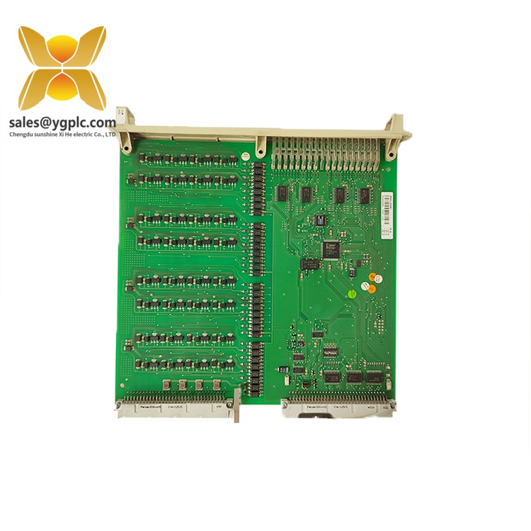
ABB Advant OCS Product Guide
ABB Advant OCS Product Guide
Load shedding
General
The load shedding system has to ensure the availability of electrical power to all essential and most critical loads in the plant. This is achieved by switching off non essential loads in case of a lack of power in the plant electrical network, or parts of the plant electrical network. A lack of electrical power can be caused by loss of generation capacity or disconnection from the public power company supply. The load shedding system for a substation in a substation node is realized with:
- one type circuit for each substation
- one type circuit for each panelhalf in the substation
- one type circuit for each sheddable load
The load shedding system can be implemented by one or more of the following functions:
- primary load shedding
- frequency load shedding
- manual load shedding
- maximum peak power demand shedding

ABB Advant OCS Product Guide
Main input to the load shedding system is the register received from another function of the ABB Advant EMS function called “Network Configuration Determination”, which determines the configuration of the electrical network. The configuration is determined from the checked breaker positions.
Secondly, load shedding needs data from the loadflow in the network. Data regarding the loads on the busses and the power generated by each generator is sent to the central load shedding function by analogue inputs and software has already checked the validity of the data. Where available, the measured power of each load is used.
This data can be received from the analogue inputs in the process controllers or via serial links to the MCC’s. When there is no power measurement available for a particular load, the belonging position of the breaker is used together with the nominal power value. Load shedding uses data representing the loadflow in the network, which is at least 2 seconds old, to prevent load shedding from using data which was obtained while the network was already in a faulty and thus unstable condition.
The third group of data needed by load shedding is the operator input. For the load shedding functionality maximum 20 priorities are used. For each load all priorities can be defined by the operator. Priority 20 is reserved for all non-sheddable loads or loads which are disabled for load shedding. Within each priority also 10 groups can be assigned. A group is the smallest sheddable unit. For each load with the load shedding option, the operator from central point of control is able to change the priority and enable/disable the load shedding function.
The operating time from opening a circuit and read in by a digital input in any of the Advant Controllers to giving the load shed command, at a particular output in any of the Advant Controllers, is maximum 150 milliseconds. For the crisis signals, the transducer reading is not used when determining whether a breaker is open. This is because of the fact the transducer takes approximately 300 milliseconds to settle, this time would make the load shedding action too slow. Preferred, if possible, a 2 out of 3 reading is to be used for the circuit breaker positions, which are used as crisis signals.