中文版

 Phone:
 Email:
 WhatsApp:
Description
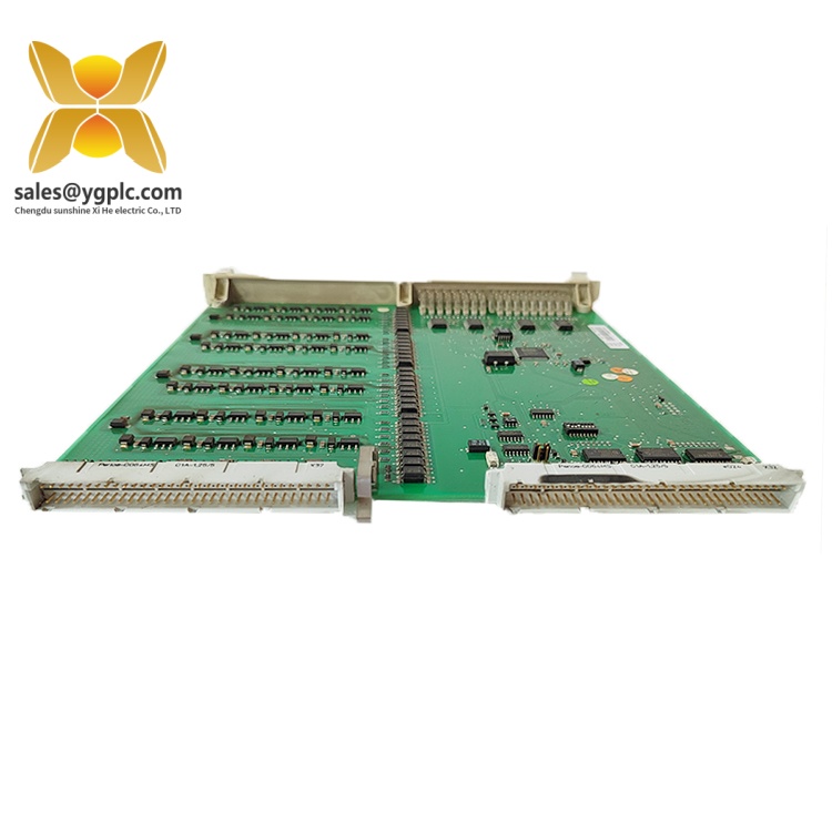
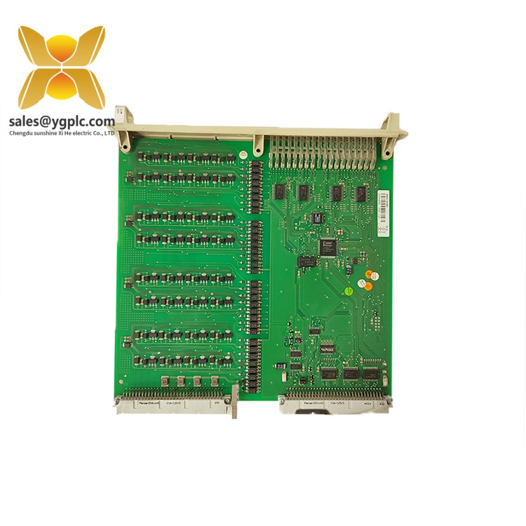
ABB DSDP140A ABB Advant OCS Product Guide PDF
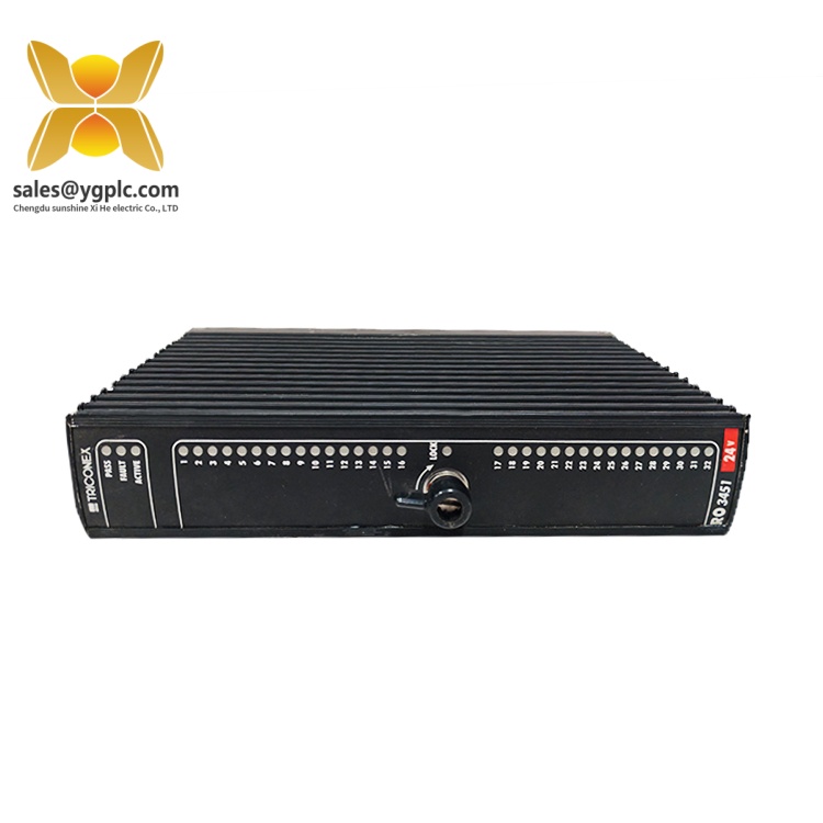
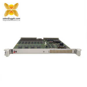
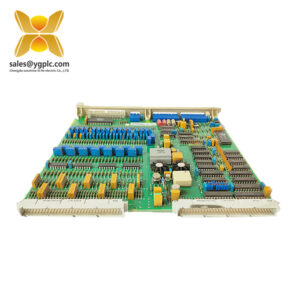
The ABB DSDP140A is a pulse counter board and positioning interface within the ABB S100 I/O system. Its catalog designation is DSDP 140A, with product identifier 57160001-ACT. The module provides an interface for one positioning loop using a pulse generator, with three pulse-input channels identified as A, B and STROBE. It is intended for integration into compatible ABB control-system architectures requiring pulse-based position interfacing and associated digital and analog signals.
The DSDP140A combines one positioning-loop pulse input, two digital inputs, four digital outputs and one analog output. The pulse inputs support signals of ±15 mA at frequencies up to 80 kHz. The digital inputs and outputs operate at 24 V DC, while the analog output provides a resolution of 11 bits plus sign and supports either 0 to +10 V or 0 to ±20 mA. These characteristics help engineers assess signal compatibility and control-system fit before selecting the module.
Key Technical Specifications
| Parameter | Specification |
|---|---|
| Brand | ABB |
| Model | DSDP140A |
| ABB type designation | DSDP 140A |
| Product identifier | 57160001-ACT |
| Product type | Pulse counter board / positioning interface |
| I/O system | ABB S100 I/O |
| Positioning loops | 1 |
| Pulse input channels | 3: A, B and STROBE |
| Pulse input signal | ±15 mA |
| Maximum pulse frequency | 80 kHz |
| Digital inputs | 2 |
| Digital outputs | 4 |
| Digital I/O voltage | 24 V DC |
| Maximum digital output current | 150 mA |
| Analog outputs | 1 |
| Analog output range | 0 to +10 V or 0 to ±20 mA |
| Analog output resolution | 11 bits + sign |
| Dimensions (D × W × H) | 209.7 × 225 × 18 mm |
| Net weight | 0.44 kg |
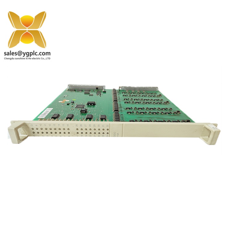
ABB Advant OCS Product Guide
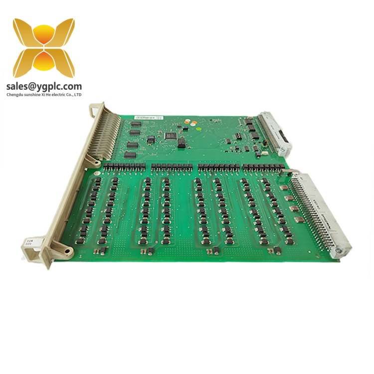
ABB Advant OCS Product Guide
Detailed Product Overview
Pulse-Based Positioning Interface
The ABB DSDP140A is designed to interface a pulse generator with an ABB S100 I/O control system. Its primary function is to support one positioning loop through three pulse-input channels: A, B and STROBE. This channel arrangement provides the signal interface required by the documented positioning-loop configuration.
The maximum specified pulse frequency is 80 kHz, with a pulse-input signal of ±15 mA. These values are important when assessing compatibility with an existing pulse generator or position-feedback device. The incoming signal characteristics and operating frequency should remain within the module’s stated limits.
Integrated Digital and Analog Signals
In addition to pulse acquisition, the DSDP140A provides two digital inputs and four digital outputs operating at 24 V DC. The digital inputs and outputs can form part of the wider control interface, subject to the application wiring and controller configuration. The specified maximum digital output current is 150 mA.
One analog output is also provided. Its documented ranges are 0 to +10 V and 0 to ±20 mA, with an 11-bit-plus-sign resolution. When integrating the module with a receiving device, engineers should ensure that the selected output range matches the receiving input’s electrical requirements. Voltage and current signals must not be treated as interchangeable wiring arrangements.
S100 I/O System Integration
The DSDP140A belongs to ABB’s S100 I/O product family. In the S100 I/O architecture, process signals are connected through dedicated connection units, and prefabricated cables link the I/O modules to the associated connection hardware. The correct connection unit, cable arrangement and cabinet wiring therefore form part of the module-selection process.
For installations integrating S100 I/O with an AC 800M controller through ABB’s S100 I/O Ethernet interface, software support is also relevant. ABB documents DSDP140A support in the S100CI846CI871HwLib hardware library, version 2.0-2, with CI846 firmware version 1.1.2.0 or higher. The documented positioning modes include POS-A(0), POS-A(1) and POS-L. These conditions apply to that specific integration arrangement and should not be generalized to every S100 I/O installation.
Replacement and Procurement Considerations
When identifying a replacement module, compare both the DSDP140A type designation and the complete product identifier, 57160001-ACT. Also compare the existing module’s pulse-input requirements, digital I/O characteristics and analog-output configuration. Confirming the controller architecture, hardware configuration and connection hardware before ordering helps reduce the risk of selecting a module that does not match the installed system.
Applications & System Role
The ABB DSDP140A occupies the process-interface layer of an S100 I/O control architecture. It connects a pulse generator to a positioning loop and provides additional digital and analog signal channels for integration into the wider control arrangement.
Its documented engineering roles include:
-
Positioning feedback interfacing: Accepts pulse signals through the A, B and STROBE channels for one positioning loop.
-
Digital signal interfacing: Provides two digital inputs and four digital outputs at 24 V DC for compatible control-system signals.
-
Analog signal interfacing: Supplies one configurable-range analog output for equipment accepting the specified voltage or current signal.
-
Control-system integration: Functions as an S100 I/O module within a compatible ABB installation, subject to controller, hardware configuration and connection-hardware requirements.
The module is a technical fit when the application requires the documented combination of one positioning loop, pulse inputs, digital I/O and an analog output. Applications requiring different pulse frequencies, signal levels or channel counts need a separate compatibility assessment.
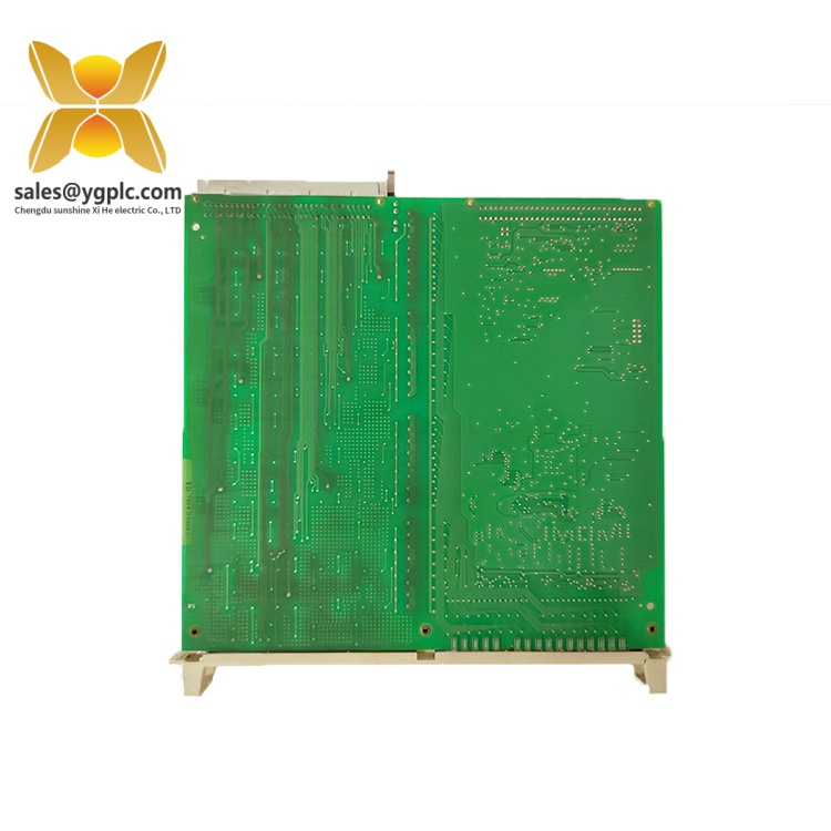
ABB Advant OCS Product Guide
Verification & Troubleshooting Notes
Before installing or replacing an ABB DSDP140A, review the following points.
1. Confirm module identity. Check the module designation and product identifier against the installed hardware records. Use DSDP140A and 57160001-ACT as the principal identification references.
2. Check the pulse-generator interface. Confirm that the wiring corresponds to the A, B and STROBE channels, that the signal is within the specified ±15 mA range, and that the pulse frequency does not exceed 80 kHz.
3. Check digital signal levels. Confirm that connected digital inputs and outputs are designed for the specified 24 V DC interface. Keep the digital output load within the documented maximum current rating.
4. Match the analog output configuration. Establish whether the receiving device requires 0 to +10 V or 0 to ±20 mA. Check the signal wiring and the receiving equipment’s input configuration before commissioning.
5. Review the I/O hardware arrangement. Confirm the S100 I/O installation, connection unit, interconnecting cable and cabinet wiring against the system documentation. Do not assume that a similar-looking module uses the same connection arrangement.
6. Check controller and software support. For an AC 800M installation using the S100 I/O Ethernet interface, check the applicable hardware library, CI846 firmware and supported positioning mode.
7. Follow approved maintenance procedures. Before handling the module or its field wiring, follow the site’s electrical isolation and equipment-maintenance procedures. Use the applicable ABB system documentation for installation and diagnostic actions.
FAQ
1. What is the ABB DSDP140A?
The ABB DSDP140A is an S100 I/O pulse counter board that provides a positioning-loop interface for a pulse generator, together with digital inputs, digital outputs and an analog output.
2. Which product identifier corresponds to the DSDP140A?
The corresponding ABB product identifier is 57160001-ACT, and the type designation is DSDP 140A.
3. What pulse input signals does the DSDP140A support?
The module provides three pulse-input channels identified as A, B and STROBE. The specified pulse-input signal is ±15 mA, with a maximum pulse frequency of 80 kHz.
4. How many digital and analog I/O channels does it provide?
The DSDP140A provides two digital inputs, four digital outputs and one analog output. The digital I/O operates at 24 V DC. The analog output supports 0 to +10 V or 0 to ±20 mA, with an 11-bit-plus-sign resolution.
5. Which ABB I/O system does the DSDP140A belong to?
The DSDP140A belongs to ABB’s S100 I/O family. Its use in an existing installation depends on the controller architecture, the configured I/O arrangement and the associated connection hardware.
6. Can the DSDP140A be integrated with an AC 800M controller?
Yes, ABB documents support for the DSDP140A in a specific AC 800M architecture using the S100 I/O Ethernet interface. The documented arrangement requires the relevant S100CI846CI871HwLib version 2.0-2 and CI846 firmware version 1.1.2.0 or higher for the stated positioning-mode support.
7. What should be checked before ordering a DSDP140A replacement?
Confirm the type designation, product identifier, pulse-generator signal requirements, digital I/O voltage, analog-output range, controller configuration and connection hardware. These checks help establish whether the module matches the installed application.