中文版

 Phone:
 Email:
 WhatsApp:
Description
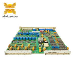
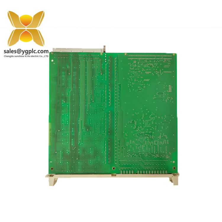
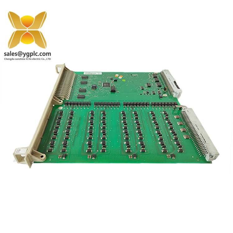
The ABB DSDO115A 3BSE018298R1 is a digital output board in the ABB S100 I/O product family, used in industrial process control systems to provide discrete output signals to field devices. It forms part of the process interface between the control system and external equipment, allowing controller commands to be delivered through the configured output circuits.
The DSDO115A is identified as a 32-channel digital output board with a 24 V DC transistor output configuration rated for up to 0.5 A per channel. Depending on the connection unit and output arrangement, the S100 I/O design also supports other documented output configurations, including higher-current transistor outputs and relay contacts. The module has a net product size of 324 × 234 × 22.5 mm and a net weight of 0.32 kg. For replacement planning, the complete order number, installed connection unit, and corresponding cable arrangement are important identification details.
Key Technical Specifications
| Parameter | Specification |
|---|---|
| Manufacturer | ABB |
| Model | DSDO115A |
| Order number | 3BSE018298R1 |
| Product type | Digital output board |
| Product family | S100 I/O |
| Digital output channels | 32 |
| Transistor output configuration | 24 V DC |
| Maximum current per channel, standard transistor configuration | 0.5 A |
| Alternative transistor output configuration | Up to 2 A with the specified DSTD 109P connection unit |
| Relay output configuration | Available with specified DSTD 108P or DSTD 108LP connection units |
| Relay output voltage range | 24–250 V AC or DC for the documented relay configurations |
| Net dimensions (D × W × H) | 324 × 234 × 22.5 mm |
| Net weight | 0.32 kg |
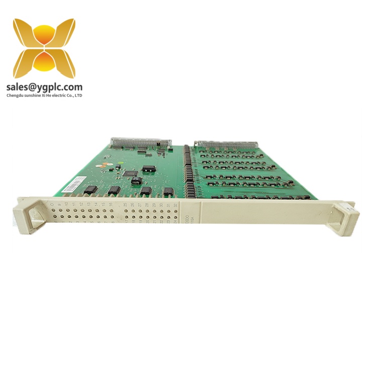
ABB Advant OCS Product Guide
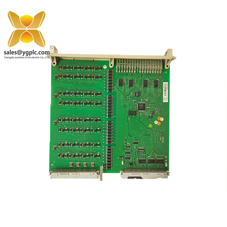
ABB Advant OCS Product Guide
The output ratings above apply to their respective configurations. They should not be treated as interchangeable ratings for every installation of the DSDO115A.
Detailed Product Overview
Digital Output Control in the ABB S100 I/O System
The ABB DSDO115A is designed to provide discrete output control within the S100 I/O architecture. A digital output interface transfers controller commands to electrical circuits connected to field equipment. Depending on the application and configured output hardware, these signals can be used to switch compatible loads or operate intermediate control circuits.
With 32 output channels, the board supports multiple discrete control points through a single I/O module. This channel capacity can simplify the organization of output signals in a centralized control cabinet, provided that the field loads, wiring arrangement, and connection hardware match the specified configuration.
Output Configuration and Load Requirements
An important selection consideration is the distinction between transistor and relay output arrangements. The documented 24 V DC transistor configuration supports a maximum current of 0.5 A per channel. A specified arrangement using the DSTD 109P connection unit supports transistor outputs rated up to 2 A. Relay-based arrangements use compatible connection units such as the DSTD 108P or DSTD 108LP and have different electrical limits.
These configurations serve different interface requirements. Transistor outputs are intended for compatible DC switching applications, while relay contacts can accommodate specified AC or DC circuits within their documented ratings. The output type, current requirements, switching characteristics, and load voltage must therefore be considered together when selecting the applicable hardware arrangement.
Connection Units and Cabinet Integration
The DSDO115A belongs to the ABB S100 I/O architecture, in which I/O boards connect to field wiring through dedicated connection units and prefabricated cables. The connection unit provides the termination interface, while the cable establishes the connection between the board and the field interface.
When installing or replacing this module, the connection unit and cable must be selected for the intended output arrangement. A matching model designation alone does not establish that an existing wiring assembly is suitable for every output configuration.
The S100 I/O architecture is associated with ABB Advant control systems and is also represented in ABB control-system documentation for S100 I/O integration with 800xA. Actual compatibility depends on the installed controller configuration, hardware revision, and system engineering requirements.
Replacement and Procurement Considerations
For maintenance and procurement, the full order number 3BSE018298R1 is a key identifier. The installed connection-unit designation is equally important when determining whether the intended replacement will support the existing field circuits.
Before approving a substitute or planning a board change, compare the existing module label, connection unit, prefabricated cable, output type, and field load ratings against the applicable system documentation. These checks help distinguish a physically similar board from a configuration that meets the required electrical and installation conditions.
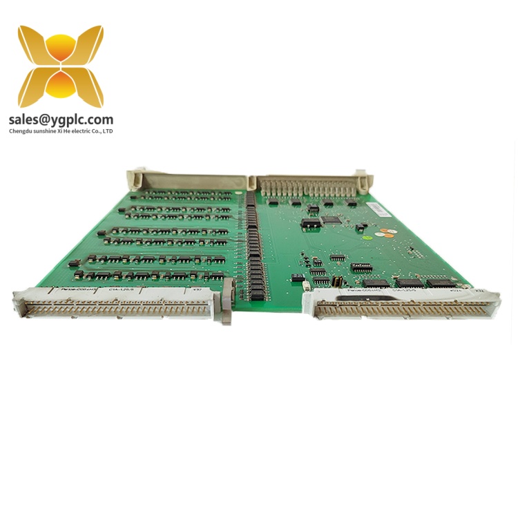
ABB Advant OCS Product Guide
Applications & System Role
The DSDO115A performs the digital output stage of the ABB S100 I/O process interface. Its function is to pass discrete control commands from the automation system to connected field circuits.
Typical engineering fit scenarios include:
-
Discrete equipment control: Switching compatible DC loads through the specified transistor output configuration.
-
Relay-based field interfaces: Connecting control signals to circuits through the applicable relay connection unit.
-
Centralized control cabinets: Grouping multiple discrete output points within an S100 I/O installation.
-
Existing ABB system maintenance: Identifying and replacing an output board where the installed S100 I/O configuration and associated connection hardware support the selected arrangement.
The DSDO115A should be selected according to the required output electrical characteristics and system configuration rather than channel count alone. The connection unit determines important aspects of the field interface and must be considered as part of the complete I/O assembly.
Verification & Troubleshooting Notes
When diagnosing an output problem or preparing a replacement, use the following checks:
-
Confirm module identity. Compare the board designation DSDO115A and order number 3BSE018298R1 with the installed hardware documentation.
-
Check the output configuration. Establish whether the installation uses transistor outputs or a relay-based arrangement, then check the corresponding connection unit.
-
Review field wiring and supply. Check the specified supply voltage, terminal assignments, wiring continuity, and load requirements against the applicable connection diagrams.
-
Check output current limits. Compare the connected load with the rating for the actual output configuration. Do not apply the higher-current rating to a different configuration.
-
Review system diagnostics. Examine available module indicators and controller alarms using the relevant system manual. An abnormal indication should be treated as a diagnostic clue, not proof of a single component failure.
-
Follow approved isolation procedures. Before inspecting wiring or changing hardware, follow the plant’s electrical isolation and maintenance procedures.
Persistent faults may involve the output board, connection unit, cable assembly, field power supply, wiring, or connected load. Diagnosis should establish the fault location before components are replaced.