中文版
中文版

 Phone:
  Email:
  WhatsApp:
 Description
- GE IS215WEPAH2BB | WEPA Series Analog I/O Pack for Wind Farm Turbine DCS Systems
Product Core Brief
- Model: IS215WEPAH2BB
- Brand: GE General Electric Automation & Controls
- Series: WEPA (Wind Energy Pitch Analog) I/O Pack, Mark VIe Turbine Control Platform
- Core Function: High-speed analog signal acquisition & closed-loop control for wind turbine blade pitch actuators
- Condition: New Original Surplus, No Refurbishment or Solder Repair Traces
- Type: Turbine Specialized Analog I/O Control Module
- Key Specs: 18–36 VDC power input | Analog servo loop processing | TMR redundant rack support
- Note: ⚠️ Original manufacturing discontinued, limited on-hand inventory
Key Technical Specifications
| Parameter Item | Technical Value |
|---|---|
| Full Part Number | IS215WEPAH2BB |
| Platform Compatibility | GE Mark VIe VME Turbine Control Rack |
| Nominal Operating Supply | 24 VDC, operating range 18–36 VDC |
| Typical Power Draw | 32 W full processing load |
| Control Loop Cycle Options | 10 ms / 20 ms / 40 ms configurable frame rate |
| Redundancy Architecture | Simplex, Dual Redundant, Triple Modular Redundant (TMR) |
| Supported Field Signals | Pitch position analog feedback, servo drive command, discrete fault contact inputs |
| Actuator Compatibility | 20 Nm / 30 Nm / 40 Nm electric & hydraulic pitch drives |
| Onboard Isolation | Galvanic isolation between backplane and field wiring circuits |
| Operating Ambient Temp | -20 °C to +70 °C (nacelle cabinet rated) |
| Storage Temperature | -40 °C to +85 °C |
| Insulation Resistance | ≥10 MΩ at 500 VDC isolation test |
| MTBF Rating | >48,000 operating hours under wind farm continuous load |
| Form Factor | Standard Mark VIe 6U VME rack plug-in module |
| Communication Interface | Internal Mark VIe backplane IONet bus, non-CANbus analog pitch variant |
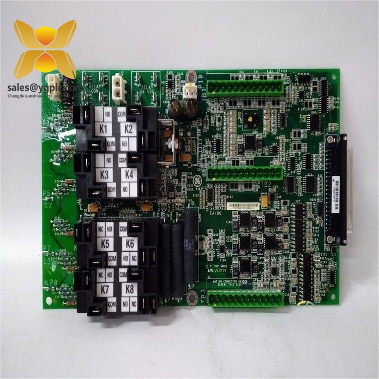
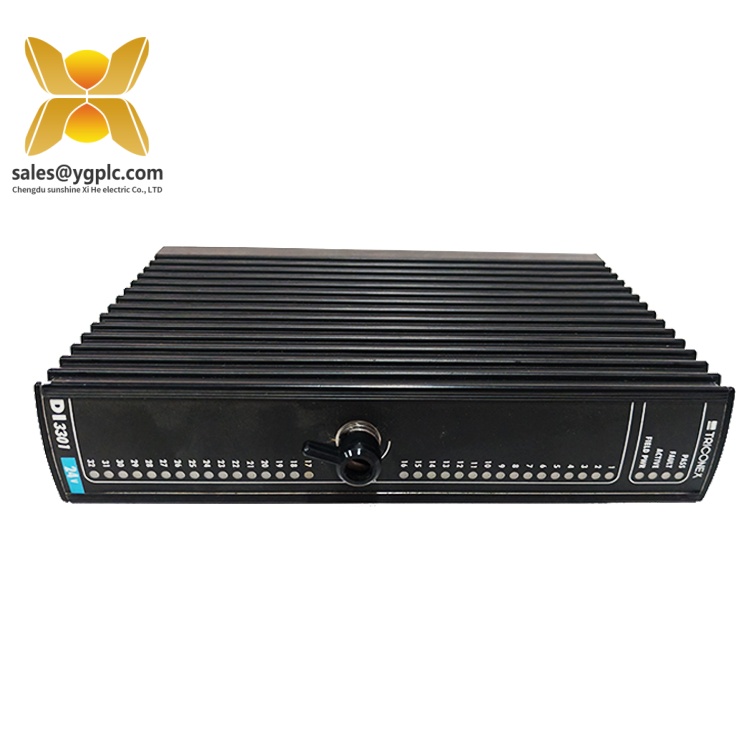
GE IS215WEPAH2BB
Product Introduction
Application Scenarios & Pain Points
Typical Application Scenarios
- Onshore Wind Farm Turbine Control – GE Mark VIe nacelle control racks for multi-megawatt wind generators. Processes pitch position feedback and outputs drive modulation signals for each rotor blade.
- Offshore Wind Turbine Cabinets – Corrosion-resistant rack-mounted control hardware, galvanic isolation suppresses marine electrical noise from hub slip rings.
- Wind Turbine Retrofit Upgrade Projects – Legacy Mark VIe platforms without CANbus pitch communication, replacing aged original WEPA packs to extend turbine service life.
- Turbine Test Bench Facilities – Factory pitch system calibration stations, simulating full range blade movement to validate actuator response curves.
- Distributed Wind Power Plants – Remote wind sites without on-site OEM service support, stocked as critical spare to avoid multi-week lead times from GE official supply chains.
Real-World Field Case
SOP Quality Transparency Inspection Process
1. Warehouse Receiving Inspection
- Source Traceability: Cross-check factory batch labels, serial number matching unit PCB marking, import customs clearance records
- Anti-Counterfeit Verification: Validate GE factory printed part marking, hologram security sticker on module front panel
- Visual Condition Audit: Inspect PCB traces for corrosion, edge connector pins for bending, casing for scratch/impact damage, no rework solder or component replacement marks
- Accessory Matching: Verify original installation drawing, rack mounting hardware and factory QC test certificate included
2. Live Bench Functional Testing
- Test Environment: Full GE Mark VIe VME test rack with IS210BPPCH1AD termination base, programmable 24 VDC power supply and analog signal simulator
- Step 1 Power Boot Self-Test: Apply 24 VDC supply, record all front panel LED boot sequence, confirm no hardware fault indicators lit
- Step 2 Backplane IONet Communication Test: Establish stable data polling between IS215WEPAH2BB and Mark VIe main CPU
- Step 3 Full Analog Loop Simulation Test: Inject full-range pitch position analog signals, verify accurate servo command output across all configured 10/20/40 ms loop speeds
- Step 4 24-Hour Continuous Load Run: Simulate cyclic blade pitch adjustment sequences, log module PCB temperature and signal drift over full test period
- Deliverable: Signed hard copy test report with signal waveform screenshots; full bench operation video provided on client request
3. Electrical Safety Parameter Testing
- 500 VDC insulation resistance test between backplane bus and field analog signal circuits, pass threshold ≥10 MΩ
- Ground continuity test for rack earthing terminals
- Dielectric withstand hipot test to validate galvanic isolation performance
4. Firmware & Configuration Backup Validation
- Read and record factory embedded firmware revision stored on onboard flash memory
- Photograph default DIP switch and rack address jumper positions for on-site commissioning reference
- Export standard pitch control parameter preset file compatible with Mark VIe control software
5. Final QC & Protective Packaging
- Secondary quality inspector cross-verify all test records and physical condition
- Place module into anti-static shielding bag and heat-seal
- Wrap with shock-absorbing bubble foam and load into reinforced export carton
- Affix QC Passed label printed with inspection date and technician ID number
Technical Pitfall Avoidance Guide
1. Mismatched WEPA Variant Communication Architecture
Avoidance Steps: Confirm original module label specifies non-CANbus architecture before ordering replacement; store separate spare stocks for CAN and non-CAN pitch systems.
Field Example: A wind farm technician substituted a CANbus WEPA pack for failed IS215WEPAH2BB last spring. The turbine stayed offline for 48 hours until correct non-CANbus spare hardware arrived.
2. Loop Timing Parameter Misconfiguration
Avoidance Steps: Record exact loop timing setting from the faulty unit’s control software before removal; reconfigure matching frame rate on replacement hardware during bench testing if requested.
3. Termination Base Model Incompatibility
Avoidance Steps: Cross-check termination base part number (IS210BPPCH1AD) before module insertion; do not mount the WEPA pack on generic Mark VIe I/O bases without matching pin mapping.
Warning: Generic analog I/O termination blocks do not carry dedicated pitch signal conditioning circuits required for this module.
4. Undersized Nacelle 24 VDC Power Supply Capacity
Avoidance Steps: Calculate total rack power consumption, reserve minimum 20% spare DC power margin; upgrade nacelle power unit if load approaches rated maximum.
Reference Data: Single IS215WEPAH2BB draws 32 W continuous, equivalent to 1.33 A at 24 VDC. Three units plus pitch actuators require minimum 10 A 24 VDC power supply.
5. ESD Damage During Nacelle Field Replacement
Avoidance Steps: Wear grounded anti-static wrist strap connected to cabinet earth bar; complete all module swaps on conductive anti-static matting. Schedule maintenance during higher humidity periods when possible.
Field Real Case: A wind farm mechanic swapped an IS215WEPAH2BB without static protection last winter. The analog feedback channel failed immediately after power application, requiring emergency air shipment of replacement spare and unplanned overtime maintenance labor.
Compatibility & Replacement Matrix
- IS215WEPAH2BB → IS215WEPAH2BB : Direct drop-in replacement (identical non-CANbus signal circuit, VME pinout, firmware platform, termination base matching)
- IS215WEPAH2BB → IS215WEPAH1BB : Partial compatibility (Same rack form factor; minor analog channel gain offset, requires control software calibration post-installation)
- IS215WEPAH2BB → IS215WEPAH3BB : Conditional compatible (Supports TMR racks; expanded signal channels, must recheck nacelle power budget before substitution)
- IS215WEPAH2BB → CANbus WEPA I/O Packs (IS215WEPAC series) : Not compatible (Different pitch communication stack, cannot interface non-CANbus analog drive hardware)
- IS215WEPAH2BB → General Mark VIe Analog I/O Packs (IS215VAAH series) : Not compatible (No dedicated pitch closed-loop processing logic, missing actuator command output circuits)